
Selecting an AC/DC switching power supply is rarely as simple as matching 230 V input to a 24 V output. The unit must start on the weakest expected mains, survive the strongest line disturbance, support the load during transients, stay within its thermal limits, and meet the safety and EMC rules for the finished equipment. A supply that looks suitable on the front page of a datasheet can still fail when installed in a warm enclosure or connected to a load with high inrush current.
This guide explains how an offline AC/DC switching supply processes energy, how its internal structure changes with power level, how a design moves from requirements to production, and which parameters engineers and buyers should verify before approval.
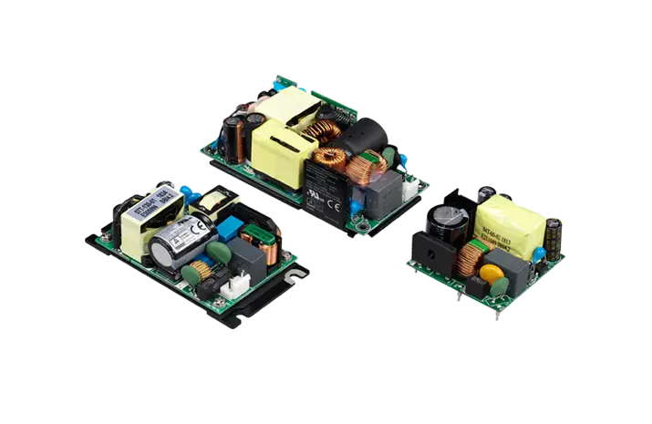
How an AC DC switching power supply works
An AC/DC switch-mode power supply first converts the alternating mains waveform into a high-voltage DC bus. It then chops that bus at high frequency, transfers energy through a transformer or inductor, rectifies the secondary waveform, and filters it into regulated DC. Feedback continuously adjusts the switching action as the input and load change.
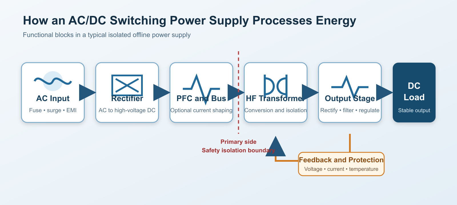
Input protection and EMI filtering
The input stage is the first line of defense. A fuse limits damage after a severe fault. A metal-oxide varistor or other surge device clamps short overvoltage events. An NTC thermistor, resistor, relay, or active circuit limits the charging current of the bulk capacitor. Common-mode chokes and X/Y capacitors reduce conducted noise while respecting leakage-current limits.
These parts must be treated as a coordinated network. A larger X capacitor may improve differential-mode attenuation but can affect discharge requirements. A larger Y capacitor may reduce common-mode noise while increasing touch current. A strong inrush limiter may run hot in continuous operation unless it is bypassed.
Rectification and the high-voltage DC bus
A full-wave bridge rectifier turns both halves of the AC waveform into pulsating DC. A bulk electrolytic capacitor stores energy between line peaks. With 230 V RMS input, the unloaded peak is approximately 325 V before losses. With universal input, the actual bus must be evaluated across low line, high line, ripple, hold-up time, and surge conditions.
The capacitor-input circuit draws narrow charging pulses near each mains peak. This creates harmonic current and raises RMS stress in the bridge, fuse, wiring, and filter. Active power factor correction is therefore common where power level, product class, or performance targets justify it. A boost PFC stage shapes input current and typically regulates a higher DC link for the downstream converter.
High-frequency conversion and isolation
The main switch, usually a MOSFET and sometimes an IGBT at higher power, converts the DC bus into high-frequency pulses. Higher frequency allows smaller magnetics, but it also increases switching loss, gate-drive demands, and EMI sensitivity.
An isolated design transfers energy through a high-frequency transformer. The transformer provides voltage conversion and contributes to the safety barrier, but it is not the whole barrier. Creepage, clearance, insulation system, PCB slots, optocouplers or isolated feedback, Y capacitors, enclosure construction, and production hipot testing all matter.
Secondary rectification output filtering and feedback
The transformer secondary produces a high-frequency waveform that must be rectified. Schottky diodes are common at lower voltages; synchronous MOSFET rectification reduces conduction loss when current is high. An output inductor and capacitor network attenuates switching ripple and supplies transient current.
Feedback compares the output with a reference and changes duty cycle, frequency, or pulse pattern. Isolated flyback supplies often use an optocoupler and shunt reference, although primary-side regulation and isolated digital techniques are also available. The loop must respond fast enough to load changes without becoming unstable.
Common internal structures and topology choices
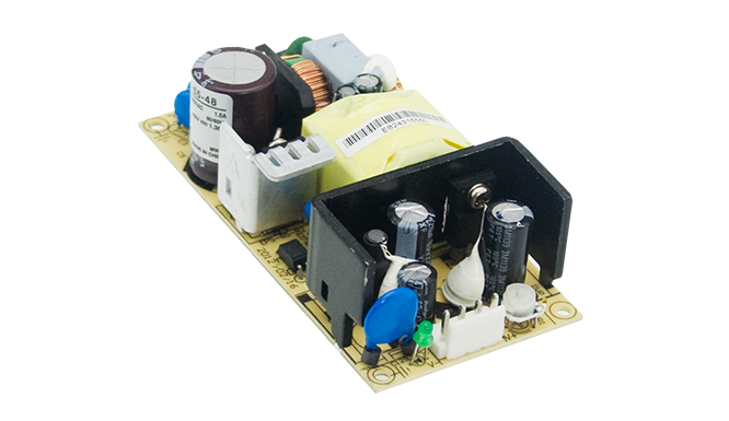
The source notes describe a chain including rectification, filtering, inversion, isolation, and output filtering. That is the right functional view, but the exact circuit depends strongly on power, input range, output requirements, and compliance targets.
| Topology or stage | Where it fits | Main strength | Design concern |
|---|---|---|---|
| Flyback | Low to moderate power, auxiliary supplies, compact adapters | Low component count and wide conversion ratio | Leakage spikes, transformer loss, ripple, and peak current |
| Forward or active-clamp forward | Moderate power and lower output current ripple | Direct energy transfer and practical transformer utilization | Reset circuit, clamp timing, and added parts |
| Half/full bridge PWM | Higher power industrial supplies | Lower switch current and scalable power transfer | Drive timing, transformer balance, and hard-switching loss |
| LLC resonant | High-efficiency, high-density designs with a controlled operating range | Soft switching and reduced switching loss | Resonant tolerances, gain range, and light-load behavior |
| Boost PFC front end | Supplies that need improved power factor and harmonic performance | Controlled input current and regulated DC link | Additional loss, control complexity, and EMI |
Single-phase input is typical for low and medium industrial power. Three-phase input becomes attractive as power rises, but there is no universal 3 kW or 5 kW boundary. Installation practice, available mains, current per phase, harmonic limits, redundancy, and customer architecture decide the crossover.
Constant-voltage operation is standard for control electronics. Constant-current operation is relevant to LEDs, battery charging, electrochemical processes, and some test systems. A product that offers both modes needs a clearly defined crossover, status indication, stability range, and protection behavior.

From requirement to production
A reliable supply is created through repeated design and verification loops, not a straight handoff from schematic to factory.
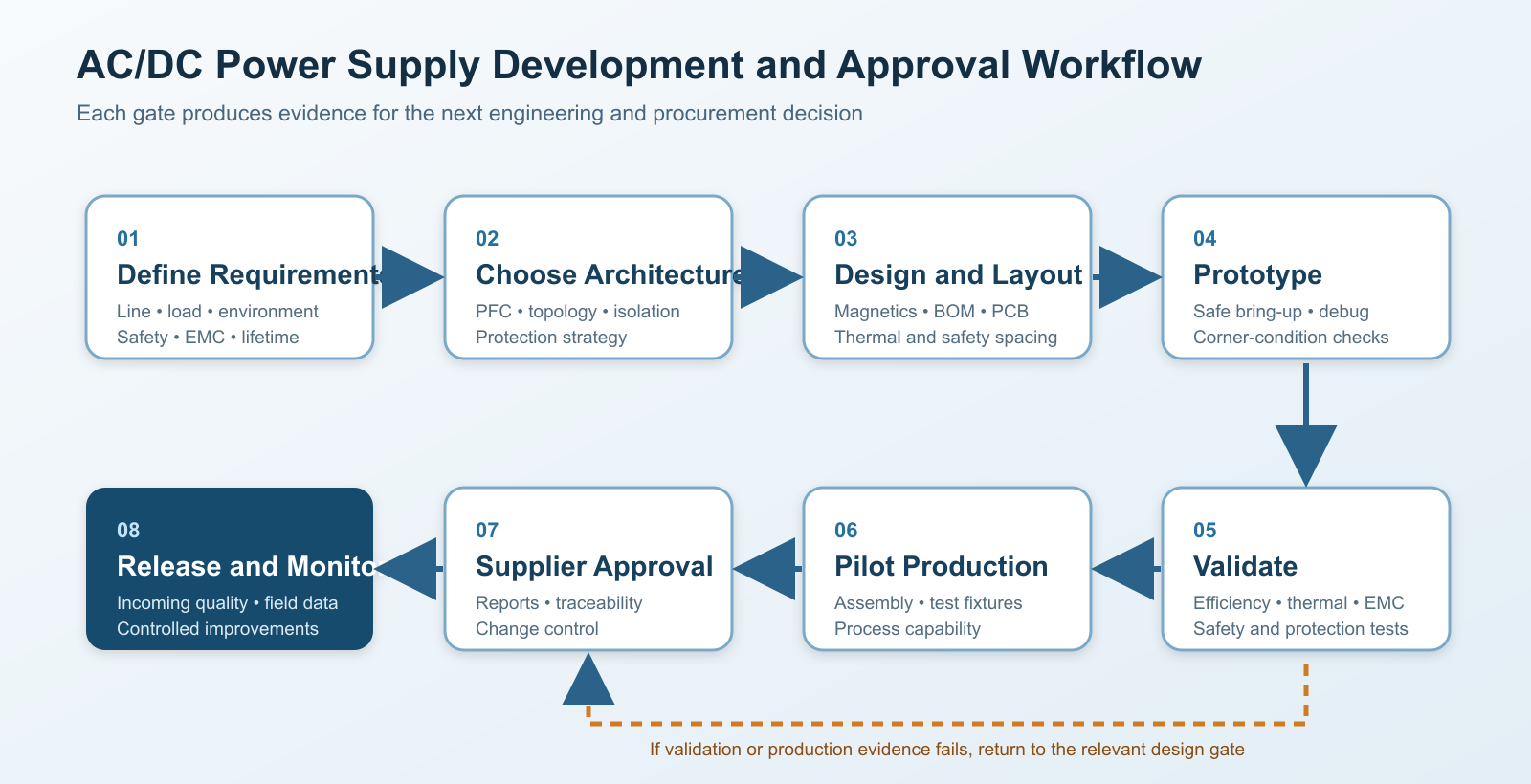
1 Define the operating envelope
Start with more than nominal voltage and current. Record input range and frequency, brownout and surge environment, output accuracy, peak load duration, load capacitance, start-up sequence, hold-up time, ambient temperature, airflow, altitude, mounting orientation, acoustic limits, lifetime goal, and applicable standards.
2 Choose the architecture and topology
Select isolation class, PFC approach, converter family, rectification method, control strategy, and protection philosophy. Estimate loss and thermal margin early. A topology that reaches the electrical target on paper may be unsuitable when height, airflow, or safety spacing is included.
3 Design magnetics and critical components
The transformer, inductors, switches, rectifiers, bulk capacitor, output capacitors, current-sense network, and snubbers carry the largest stress. Calculate voltage and current extremes rather than selecting from nominal values. Account for tolerance, temperature, aging, saturation, transient energy, and supplier variation.
4 Capture the schematic and create the BOM
The schematic should include protection, sensing, test points, discharge paths, and component ratings. The bill of materials should identify approved alternates and the limits that make an alternate acceptable. Substituting a capacitor with the same capacitance but different ESR, ripple rating, or lifetime can change the product substantially.
5 Lay out the PCB around current loops and safety barriers
Keep high di/dt loops compact. Separate noisy switching nodes from feedback and sensing. Give gate drive and current sense short, deliberate return paths. Maintain creepage and clearance around the isolation barrier, and use slots only where manufacturing and contamination controls support them. Thermal vias, copper spreading, component spacing, and airflow must follow the loss model.
6 Build and debug prototypes safely
Bring-up should use current-limited sources, isolation practices, differential probes, and a written test sequence. Verify start-up, shutdown, no-load operation, current limit, short circuit, overvoltage, brownout, and recovery before extended full-power tests.
7 Validate performance and compliance margins
Measure line/load regulation, ripple, transient response, efficiency, power factor, harmonic current, inrush, hold-up, thermal rise, conducted/radiated emissions, surge, EFT, ESD, dielectric strength, and grounding where applicable. Test at corners of the operating envelope, not only at room temperature and nominal line.
8 Transfer the design into controlled production
Pilot builds reveal soldering, winding, assembly, programming, and test-fixture problems that prototypes hide. Production should define incoming inspection, transformer checks, automated or guided functional tests, hipot and ground-bond tests where required, burn-in or screening strategy, traceability, and engineering change control.
Selection parameters that deserve a real check
Input requirements
Confirm the rated AC range, frequency range, phase, maximum input current, power factor, harmonic-current performance, inrush, leakage current, surge rating, and brownout behavior. “Universal input” often means 85-264 VAC, but the usable output power may be derated at low line. If the datasheet also lists a DC input range, verify polarity, protection, switching behavior, and whether all safety approvals remain applicable.
Output requirements
Calculate continuous power and transient demand separately. Motors, valves, capacitive electronics, lamps, and DC/DC converters can draw short peaks that exceed steady current. Review output tolerance, line/load regulation, ripple and noise measurement bandwidth, remote-sense limits, minimum load, parallel operation, current sharing, and start-up into capacitive loads.
Efficiency thermal derating and lifetime
Peak efficiency is not enough. Request an efficiency map over expected line and load. Heat inside the installed enclosure determines junction temperature and capacitor life. Derating curves must match the actual airflow, orientation, altitude, and ambient temperature.
Protection behavior
Overcurrent protection may be constant current, foldback, hiccup, or shutdown. Each behaves differently with motors, large capacitors, and parallel loads. Also confirm overvoltage, overtemperature, short-circuit recovery, input undervoltage, and whether protection is latching or automatic.
Safety and EMC evidence
CE marking alone is not a universal third-party safety approval. Ask which product safety standard and edition apply, which certification body issued the report, and which model variants are covered. Review insulation class, working voltage, pollution degree, overvoltage category, altitude, leakage current, touch-current conditions, and the final system responsibility.
| Selection area | Minimum information | Common mistake |
|---|---|---|
| Input | Range, frequency, phase, inrush, PF/THD, surge | Assuming full output at the lowest line voltage |
| Output | Continuous and peak current, ripple, transient response | Sizing only from average load |
| Thermal | Efficiency map, derating, airflow, orientation, altitude | Using room-temperature bench data for a sealed cabinet |
| Safety | Standard, report scope, insulation, hipot, leakage | Treating a logo as proof for every application |
| EMC | Conducted/radiated limits and immunity levels | Ignoring cable length and system grounding |
| Reliability | Component temperatures, capacitor basis, change control | Comparing MTBF numbers calculated by different methods |
Design and integration precautions
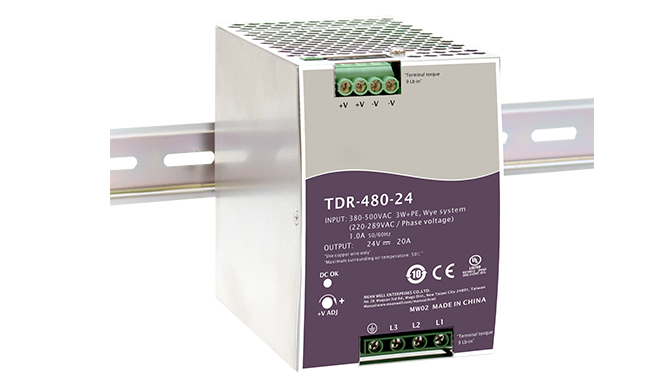
Leave thermal margin. Do not place the supply against a hot drive, transformer, or sealed wall without checking local air temperature. Maintain the clearances and mounting direction used for the derating data.
Protect signal circuits from switching noise. Route analog sensors and communication lines away from input filters, switch nodes, transformers, and output rectifier loops. Bond protective earth and chassis deliberately; an improvised ground path can worsen both emissions and immunity.
Treat isolation as a system property. Field wiring, connectors, mounting hardware, heat sinks, shields, and test points can bridge a carefully designed PCB barrier. Confirm accessible voltages under normal and single-fault conditions.
Control inrush and load start-up. The AC input may trip an upstream breaker when several supplies start together. At the output, a large capacitive load can trigger hiccup protection. Sequence tests should use the real load or a representative emulator.
Measure ripple correctly. A long oscilloscope ground lead can show noise that is mostly probe pickup. Use the bandwidth and probe method stated by the supplier, then repeat with the system cabling to understand installation effects.
Plan component availability without weakening the design. Approved alternates should be qualified for electrical stress, thermal behavior, safety recognition, mechanical fit, and EMC impact. Procurement changes need engineering review.
Buyer approval checklist
Before releasing an AC/DC supply for a new product, collect the following evidence:
A complete datasheet with operating conditions for every key rating.
Efficiency, derating, ripple, transient, inrush, and hold-up curves at relevant line conditions.
Safety certificates and reports that cover the exact model and end-use category.
EMC test evidence plus the recommended external filter and grounding configuration.
Critical-component list, production test plan, traceability method, and change-notification policy.
Samples tested in the actual enclosure with real wiring and representative load transients.
Conclusion
An AC/DC switching power supply is a chain of interdependent functions: protection and filtering, rectification, optional PFC, high-frequency conversion, isolation, output rectification, filtering, and feedback. Its quality is revealed at the boundaries - low line, high temperature, load steps, surge events, EMC tests, and production variation.
For OEM and industrial projects, begin with the complete operating envelope and the compliance plan. Then compare candidate supplies using measured curves and installation-specific tests rather than headline wattage alone. SIPURUI can help match AC/DC power-supply options to input conditions, load behavior, enclosure limits, and production requirements while keeping brand selection secondary to the engineering fit.