
Power noise that looks insignificant on a general-purpose load can become visible data error in a diagnostic instrument. An ECG front end may be working with microvolt-level biopotential signals. An ultrasound platform must keep sensitive analog acquisition, high-speed digital processing and a display subsystem operating in the same enclosure. In both cases, the AC/DC supply is part of the signal-integrity problem, not a box to select at the end of the design.
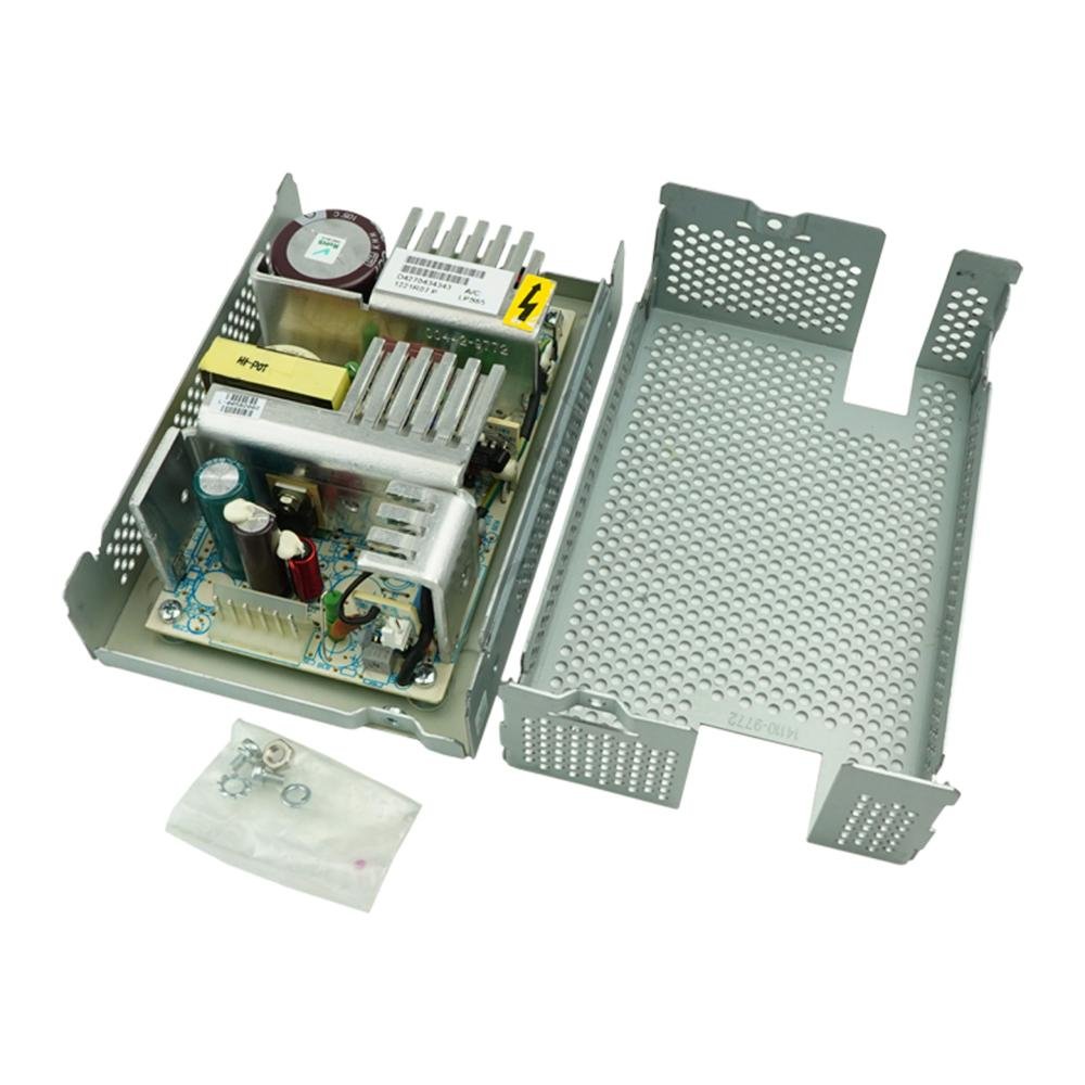
SIPURUI's new 65 W enclosed AC/DC power supply was developed for this kind of noise-sensitive equipment. Its published specifications focus on low output ripple, low leakage current, low output-to-earth floating voltage and useful EMC margin in a compact, fanless enclosure. Two standard outputs are available: 12 V at 5.42 A and 24 V at 2.71 A.
Why ordinary power-supply selection rules fall short
A conventional industrial supply is often evaluated around output voltage, rated current, efficiency, temperature and price. Those checks still matter in medical equipment, but they do not describe how the supply interacts with a patient-connected or measurement-sensitive system.
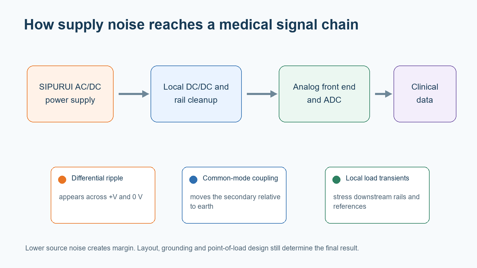
Three coupling paths deserve attention. Differential ripple appears directly across the DC output. Common-mode noise can move the secondary relative to protective earth. Capacitive current can also cross the isolation barrier through intentional Y capacitors and unavoidable transformer capacitance. Increasing the capacitance of an EMI filter can improve emissions while consuming more of the equipment's leakage-current budget. Reducing that capacitance may lower leakage but make conducted-emissions work harder. This is a design tradeoff, not a single-component fix.
Linear supplies remain attractive when exceptionally quiet rails are needed, but their transformer size, heat dissipation and conversion loss are difficult to justify in compact equipment. A switch-mode supply can be smaller and more efficient; the challenge is controlling its high-frequency energy well enough that downstream filters and low-noise regulators are practical rather than heroic.
What low ripple changes in a medical signal chain
Ripple is rarely a clean sine wave. The measurement can contain the switching fundamental, harmonics, rectifier-related components and narrow high-frequency spikes. A single millivolt value is useful only when the bandwidth, probe connection, load, input voltage and measurement point are known.
That detail matters for ECG equipment. The front end has high gain and must reject mains-related interference while preserving low-amplitude physiological signals. Supply noise that enters through the analog rail, reference, ground network or cable shield can raise the noise floor or create repeatable artifacts. The system may still boot and pass a basic functional check while producing a worse trace.
Ultrasound equipment presents a different load profile. Transmit pulses, receive electronics, digital processing and displays can produce fast changes in current. Designers therefore need both a low steady-state noise floor and acceptable transient response. A low-ripple AC/DC stage reduces the burden on downstream conversion, but it does not remove the need for local decoupling, rail sequencing or point-of-load regulation.

Published specifications for the new product
The manufacturer's release lists the following nominal data. Values marked as typical or promotional claims should be checked against the current datasheet and a sample tested under the intended operating conditions.
| Model | Rated power | AC input | DC output | Rated output current | Efficiency | Typical ripple/noise | Enclosure size |
|---|---|---|---|---|---|---|---|
| 12 V version | 65 W | 85-264 VAC | 12 VDC | 5.42 A | 82% | 0.2 mV | 140 × 70 × 42 mm |
| 24 V version | 65 W | 85-264 VAC | 24 VDC | 2.71 A | 85% | 0.2 mV | 140 × 70 × 42 mm |
The launch graphic also identifies a full-load ripple target of no more than 1 mV, touch leakage current of 75 µA, floating voltage as low as 35 mV and isolation capacitance of 9 pF. It states EN 55032 Class B emissions performance with more than 10 dB of margin and tolerance of a 305 VAC momentary overvoltage. These figures are promising, but a buyer should request the exact test setup, limit line, detector, cable arrangement, grounding configuration and sample conditions before using them in a compliance plan.
Leakage current, floating voltage and isolation are related but different
"Low leakage" is often used too loosely. Earth leakage, touch current and patient leakage describe different current paths. The relevant limit also depends on equipment class, applied-part classification, normal condition, single-fault condition and the complete system configuration.
The AC/DC module is not itself an applied part. A power supply with low measured leakage can help the system budget, but it does not make the finished equipment Type B, BF or CF compliant. Data interfaces, shields, chargers, secondary DC/DC converters and multiple supplies can create additional paths. The end product still needs a leakage-current and dielectric-strength assessment in its final enclosure with its intended accessories.
Low output-to-earth capacitance and low floating voltage are helpful because they reduce common-mode coupling into sensitive circuits. They are especially relevant when the analog ground cannot simply be bonded to protective earth. The final grounding strategy must still be defined at system level; an accidental connection through a USB cable or test instrument can completely change the result seen on the bench.
EMC margin can shorten debugging, but it is not system certification
Component-level emissions margin gives the equipment designer room for wiring, load converters and enclosure resonances. It can also reduce the chance that a late input-filter change increases leakage current. A stated 10 dB margin is therefore useful engineering information.
It is not a guarantee that the finished medical device will pass. Cable length, chassis bonding, switching loads, display interfaces and installation geometry can move an emissions trace by several decibels. Immunity is a separate question. The US FDA's current EMC guidance expects manufacturers to assess the electrically powered device and document the testing used in a submission; a compliant component cannot replace that system evidence.
For a medical product, ask for reports that correspond to the actual orderable part number. Confirm whether a statement means certified, evaluated, designed to meet or merely tested by the manufacturer. IEC/EN 60601-1 is the central medical electrical safety framework; IEC/EN 60601-1-2 addresses EMC for medical electrical equipment. UL/EN 62368-1 and EN 61558 or EN 60335 can be relevant to other product categories, but they are not substitutes for the medical equipment assessment.
ECG integration example
An ECG application can place the new AC/DC supply ahead of charging control, a battery pack and downstream DC/DC conversion. The sensitive path contains the electrode input, input protection, a buffer amplifier, lead selection and pulse-width or pulse-frequency control. That architecture illustrates an important point: the AC/DC supply can establish a cleaner baseline, while local conversion and layout finish the job close to the analog electronics.
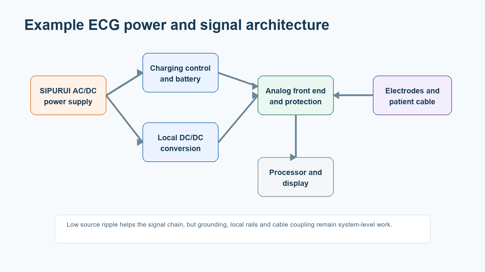
Example ECG power and signal architecture using the new SIPURUI supply. This is an application concept rather than a complete reference design. Original technical graphic created for this article.
During prototype work, measure the supply in at least two ways. First, use a short ground spring or coaxial connection and a defined bandwidth to establish the rail's differential ripple. Then observe the analog acquisition result under representative lead impedance, load steps, battery charging and all communication cables attached. A clean power-supply waveform does not prove that common-mode current is absent, and a noisy scope capture made with a long ground clip does not prove that the supply is bad.
A practical qualification plan
Treat the power supply as a component in the equipment risk and verification plan. Start with the published data, then build evidence around the real operating modes.
| Qualification item | Why it matters | Evidence to request or test |
|---|---|---|
| Ripple and noise | Protects analog SNR and avoids visible artifacts | Scope plots at low line/high line, no load/full load and dynamic load; bandwidth and probe method stated |
| Touch and earth leakage | Consumes part of the system safety budget | Test report at rated mains frequency and worst-case input; normal and relevant single-fault conditions |
| Isolation capacitance / floating voltage | Affects common-mode current into secondary circuits | Defined measurement circuit plus results with PE connected and disconnected as applicable |
| Conducted and radiated emissions | Determines available EMC margin | Actual limit-line plots, detector type, LISN setup, cable layout and enclosure configuration |
| Immunity behavior | Prevents reset, corruption or unsafe output during disturbances | System tests to the applicable IEC 60601-1-2 environment and performance criteria |
| Thermal derating | Confirms 65 W is usable in the real enclosure | Temperature rise and derating data at maximum ambient, altitude and mounting orientation |
| Safety approvals | Reduces certification uncertainty | Current certificates, CB report, critical-component list and model-number traceability |
| Change control | Prevents a silent BOM change from invalidating evidence | PCN policy, revision identification and supplier quality agreement |
Questions to settle before placing a production order
An engineering sample should match the production suffix, PCB revision and safety file. Ask whether the 0.2 mV figure is RMS, peak-to-peak or derived using another method, and confirm the stated bandwidth. For the 10 dB emissions margin, request the plots rather than a pass/fail table. Check whether the 75 µA value is earth leakage or touch current and at which mains voltage and frequency it was measured.
Procurement should also look beyond the electrical headline. Confirm lead time, minimum order quantity, lifecycle status, substitution policy and the supplier's response to component changes. For equipment sold in several regions, map the 85-264 VAC input range to the intended mains cord, fuse, connector and overvoltage category. A universal input marking does not complete the regional compliance work.
A useful starting point, not a shortcut around validation
SIPURUI's new low-ripple power supply addresses a real gap between bulky linear supplies and general-purpose switch-mode units that need extensive external filtering. Its combination of a 65 W enclosed format, universal input, published sub-millivolt ripple and low-leakage design makes it a credible candidate for ECG, ultrasound and other measurement-sensitive platforms.
The right next step is a controlled evaluation, not an immediate production substitution. SIPURUI can support sample selection and application discussions for the 12 V and 24 V versions. Equipment manufacturers should qualify the chosen model in the final grounding, cable, load and enclosure configuration, then retain the resulting evidence in the device technical file.