
The term switching power supply appears on everything from a phone charger to a PLC cabinet, yet those products can look and behave very differently. That is where purchasing teams and even experienced equipment designers can get crossed up: “switching” describes the way power is converted, while labels such as DIN rail, open frame, constant-current, and flyback describe different parts of the design.
This guide answers two practical questions: what makes a power supply a switch-mode design, and what are the useful ways to classify one? The short answer is that a switching power supply regulates energy by rapidly turning semiconductor devices on and off. Its topology, mechanical format, and output-control method should then be chosen separately to suit the load and installation.
What Is a Switching Power Supply?
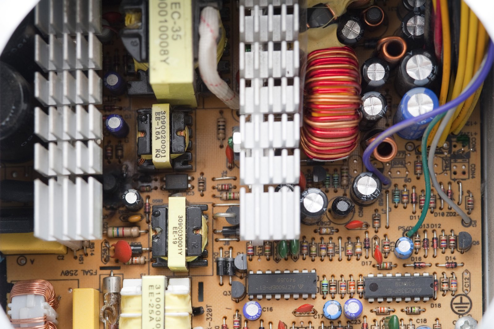
A switching power supply, also called a switch-mode power supply or SMPS, converts electrical power by operating one or more semiconductor switches at high frequency. A controller adjusts the duty cycle, frequency, phase, or another switching variable so the output remains within its target range as the input and load change.
In a typical AC-DC unit, the incoming AC is first rectified. A high-voltage DC bus then feeds a switching stage. That stage transfers energy through inductors, transformers, capacitors, and rectifiers before the output filter delivers usable DC. Feedback closes the loop by comparing the actual output with a reference and correcting the switching action.
This definition is more precise than relying on visible features. A small enclosure, universal AC input, or an efficiency figure above 80% is common in modern SMPS products, but none of those features alone defines the technology. A switching supply can be large, designed for a narrow input range, or optimized for an operating point other than peak efficiency.
Why High-Frequency Switching Changes the Design
The semiconductor switch spends most of its time either fully on or fully off. In those states, its power loss can be much lower than that of a pass device continuously dropping excess voltage. Higher switching frequency also allows smaller magnetic components and filters for a given power level, although higher frequency increases switching loss, EMI pressure, and layout sensitivity.
The result is a design tradeoff rather than free efficiency. Power density, cooling, EMI, cost, hold-up time, transient response, and component stress all influence the final product. Texas Instruments recommends starting topology selection with a specification that includes input range, output voltage, maximum load, isolation, temperature, compliance, and the main performance priority .
Switching Power Supply vs Linear Power Supply
A linear regulated power supply uses a pass element in its active region to remove the difference between input and output voltage. It may also use a low-frequency mains transformer before rectification. This approach can provide low output noise and straightforward control, but the voltage dropped across the pass element becomes heat.
An SMPS moves energy in controlled pulses and then filters the result. That usually improves efficiency and power density, especially when the input-to-output voltage difference is large. The switching edges, however, create conducted and radiated noise that must be managed through topology, magnetics, PCB layout, shielding, and filtering.
| Decision factor | Switching power supply | Linear regulated power supply |
|---|---|---|
| Efficiency and heat | Usually higher efficiency, with less heat for the same delivered power | Loss rises with input-output voltage difference and load current |
| Size and weight | High-frequency magnetics support compact designs | A 50/60 Hz transformer and heat sink can be bulky |
| Output noise | Requires ripple and EMI control | Often favored for very low-noise rails |
| Input range | Wide-range AC models are common, but not universal | Commonly designed around a narrower transformer input |
| Design complexity | More components, control behavior, and EMI work | Simpler regulation concept |
| Typical B2B use | Automation, networking, lighting, chargers, embedded equipment | Precision analog, laboratory, audio, and noise-sensitive stages |
“Linear versus switching” is therefore not a contest with one permanent winner. The right choice depends on thermal budget, noise tolerance, efficiency requirements, volume, compliance, and total system cost. Some equipment uses an efficient SMPS for the main conversion stage and a low-noise linear regulator for a sensitive local rail.
The Main Types of Switching Power Supply
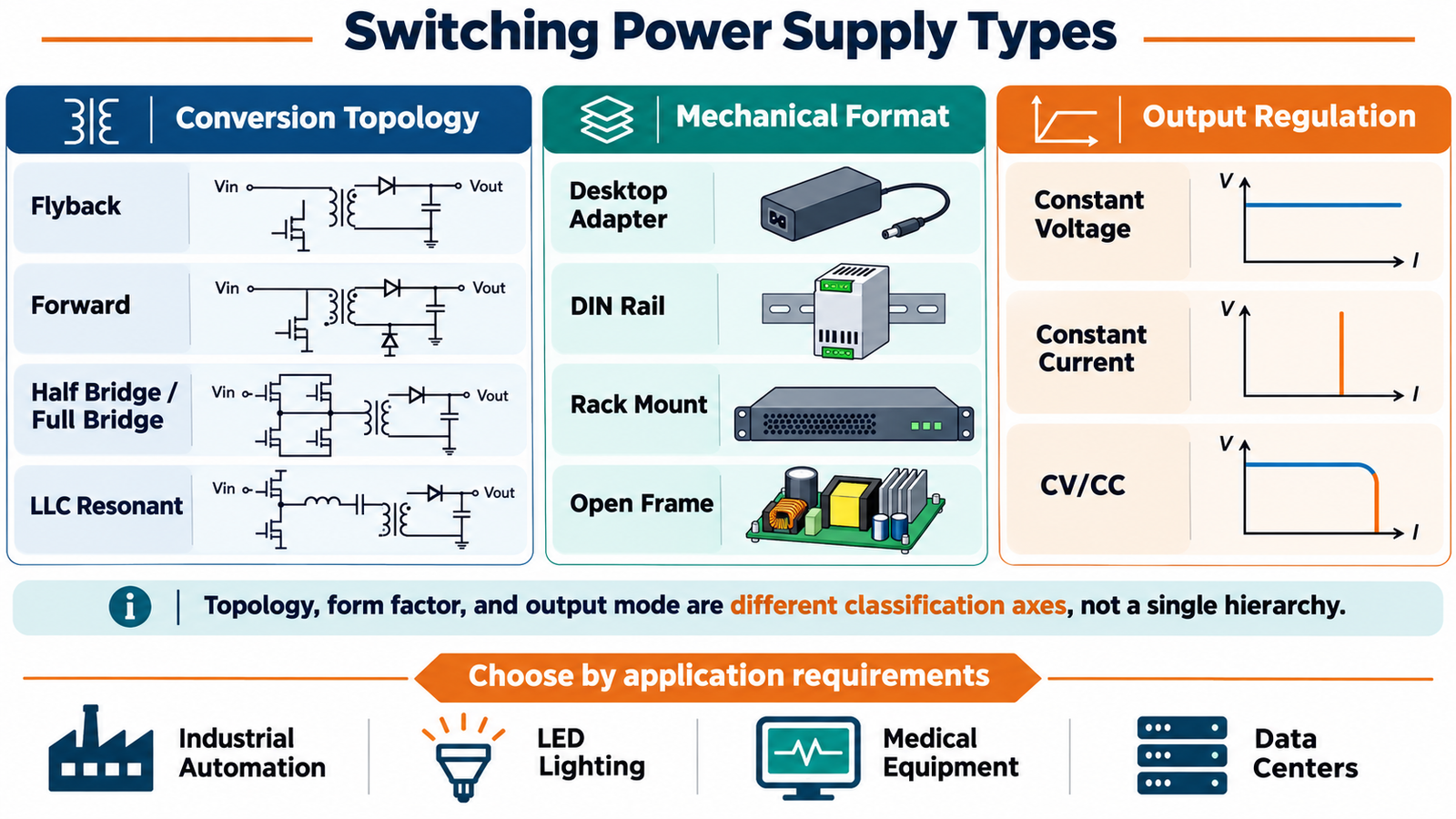
The cleanest way to understand SMPS types is to separate three classification axes. A product might simultaneously be an LLC converter, a rack-mount unit, and a constant-voltage supply. Those labels are complementary, not competing definitions.
1. Types by Conversion Topology
Topology describes the electrical power stage. It determines how the switch, magnetic components, rectifiers, and capacitors exchange energy. Power range is useful as an initial clue, but it is not a rigid boundary. Input voltage, output current, isolation, efficiency target, semiconductor technology, cooling, switching frequency, and cost can move the practical limits.
| Topology | Where it fits well | Main advantages | Watch points |
|---|---|---|---|
| Flyback | Low-power isolated AC-DC and DC-DC supplies, auxiliary rails, adapters | Low component count, multiple outputs possible, wide input capability | Transformer leakage spikes, EMI, output ripple, and increasing stress at higher power |
| Forward | Isolated supplies where output current and power exceed a basic flyback's comfortable range | Energy transfers to the secondary during the on-time; output ripple and current stress can be favorable | Requires transformer reset and an output inductor; more parts than flyback |
| Half bridge or full bridge | Medium- to high-power converters, telecom, servers, industrial systems | Better use of transformer core and switch voltage stress; suitable for higher power | More switches, gate-drive complexity, shoot-through control, and higher BOM cost |
| LLC resonant | High-efficiency isolated converters, especially where power density matters | Soft switching can reduce switching loss and EMI; strong efficiency potential | Variable-frequency control, resonant-tank design, and light-load behavior need care |
Flyback
The flyback is common because it combines energy storage and isolation in one coupled magnetic component. When the primary switch is on, energy builds in the magnetizing inductance. When the switch turns off, energy moves to the secondary. TI describes it as a workhorse for low-power isolated conversion and notes that a conventional design is commonly used around the 100 W class, while specialized active-clamp and soft-switching variants can go higher .
That is why flyback designs appear in adapters, standby supplies, industrial auxiliary rails, and compact chargers. The often-repeated “below 150 W” rule is a rough purchasing shortcut, not an engineering limit.
Forward
A forward converter transfers energy to the output while its primary switch is on. Unlike a flyback, it uses an output inductor to smooth the secondary current and needs a method to reset the transformer core. It becomes attractive when higher output current or lower ripple makes a simple flyback less comfortable.
Forward-derived designs are used in industrial and embedded power, but the boundary between flyback and forward is application-specific. Buyers should compare verified efficiency, thermal rise, regulation, and transient data instead of selecting solely by a wattage label.
Half Bridge and Full Bridge
Bridge topologies divide the input bus across multiple switches and drive the transformer in both directions. Half-bridge and full-bridge families are widely used when power, current, and transformer utilization justify added control and gate-drive complexity. Phase-shifted full bridge is one important high-power variant.
These topologies suit rack power, communications infrastructure, charging systems, and other high-power platforms. They are not automatically “better”; at low power, the extra switches and control burden can add cost without enough system benefit.
LLC Resonant
An LLC converter uses resonant inductive and capacitive elements to shape current and enable soft-switching over a useful operating range. Reduced switching loss can support high efficiency and power density. LLC is popular in server, display, industrial, and high-performance adapter platforms, but it is not simply a premium replacement for every hard-switched converter. Regulation range, hold-up requirements, start-up, light-load operation, and magnetic design still matter).
2. Types by Mechanical Format
Mechanical format answers a different question: how will the supply be installed, cooled, wired, protected, and serviced?
Desktop and Wall-Mount Adapters
External adapters keep mains voltage and heat outside the end equipment. They are common in networking, instrumentation, point-of-sale systems, and portable products. Procurement details include plug style, DC connector, cable length, grounding class, regional approvals, no-load consumption, and whether the adapter will be replaced in the field.
DIN Rail Power Supplies
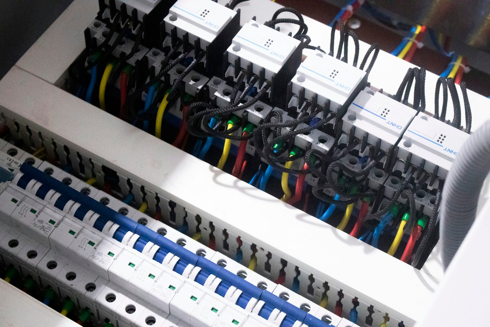
DIN rail supplies mount directly inside industrial control panels. Their narrow profile, touch-safe terminals, adjustable 24 V output, status contacts, redundancy options, and cabinet-friendly wiring make them a practical choice for PLCs, sensors, relays, HMIs, and control networks.
The keyword data supplied for this project shows strong search interest in DIN rail power supply and 24V DIN rail power supply. Those phrases are useful, but voltage is only the start. Panel designers must also check ambient derating, installation spacing, short-circuit behavior, inrush current, DC OK signaling, series or parallel operation, and the available branch protection.
Rack-Mount Power Supplies
Rack systems serve data centers, telecommunications, laboratories, and centralized industrial equipment. They may support hot swap, N+1 redundancy, current sharing, remote monitoring, and front-to-back airflow. In this category, service strategy and system architecture can matter as much as the efficiency of one converter module.
Open-Frame and Enclosed Supplies
Open-frame supplies are intended for integration inside end equipment. The equipment designer remains responsible for protective enclosure, airflow, spacing, grounding, EMC, and system certification. Enclosed supplies add a protective case, often with screw terminals, but they still require correct mounting and ventilation. Manufacturer installation guidance commonly calls for output derating at high ambient temperature or nonstandard mounting orientation.
3. Types by Output Regulation
Output mode must match the electrical behavior of the load. Confusing constant voltage and constant current can cause poor performance or damage.
Constant-Voltage Supplies
A constant-voltage supply regulates its output to a set voltage while the load determines current, up to the supply's limit. Common outputs include 5 V, 12 V, 24 V, and 48 V. This is the normal choice for controllers, communication equipment, sensors, embedded electronics, and many LED strips that include their own current-limiting elements.
Constant-Current Supplies
A constant-current supply adjusts its output voltage to maintain a target current through the load. It is widely used for LED strings and other loads whose operating voltage varies. The load's full voltage range must remain inside the driver's compliance window. “600 mA” alone is not enough information; the minimum and maximum output voltage, maximum wattage, dimming method, and isolation requirements must also match.
CV/CC Supplies
A CV/CC supply operates in constant-voltage mode until current reaches the programmed limit, then transitions into constant-current regulation. Bench supplies, battery chargers, test systems, and some LED applications use this behavior. For battery charging, CV/CC capability does not replace a chemistry-specific charging profile, temperature controls, or a battery-management system.
Application Categories Are Requirements, Not Topologies
“Industrial,” “medical,” “LED,” and “data-center” describe application environments. They do not identify one circuit. Each environment adds its own safety, EMC, reliability, thermal, control, and documentation requirements.
| Application | Typical format and output | Selection priorities beyond voltage and wattage |
|---|---|---|
| Industrial automation | DIN rail or enclosed, usually constant voltage | Derating, surge and transient immunity, DC OK signal, redundancy, terminal access, wide temperature range |
| LED lighting | Enclosed or potted driver, constant current or constant voltage | Dimming compatibility, flicker, load window, ingress protection, surge rating, thermal case limit |
| Medical equipment | Enclosed or open frame, often multiple regulated outputs | Means of protection, leakage current, isolation, EMC classification, risk-management documentation |
| Data center and telecom | Rack or modular, usually constant voltage | Hot swap, redundancy, efficiency across load, telemetry, airflow, power density, fault containment |
| Embedded equipment | Open frame or board mount | Mechanical clearance, airflow, conducted EMI, standby power, connector and harness design |
A Practical Selection Checklist
Start with the load, not with a topology name. Record the normal and peak voltage/current demand, transient profile, start-up behavior, and whether the load needs constant voltage, constant current, or CV/CC operation. Then define input range, frequency, phase, brownout behavior, ride-through, and surge environment.
Next, decide whether the output needs isolation and what insulation level the end product requires. Add the real thermal conditions: maximum cabinet temperature, altitude, airflow, mounting orientation, nearby heat sources, and acceptable case temperature. A nominal 100 W supply may not deliver 100 W in a sealed 60°C enclosure.
Finally, review compliance and integration. Check safety approvals against the end-product standard and target markets, examine conducted and radiated EMI data, and confirm creepage, clearance, grounding, fusing, branch protection, connectors, and service access. Obtain efficiency, ripple, transient, hold-up, inrush, derating, and lifetime data under conditions close to the intended application.
| Buyer question | Evidence to request |
|---|---|
| Will it deliver rated power in our enclosure? | Derating curves by temperature, input voltage, altitude, and orientation |
| Will the load start reliably? | Peak-current capability, hiccup or constant-current behavior, start-up waveform |
| Will it pass system EMC tests? | Test reports, filter recommendations, layout and grounding guidance |
| Is it approved for our market and product class? | Current certificates with exact model numbers and applicable standards |
| Can we maintain supply over the product lifetime? | Component-life assumptions, warranty, change-control process, and second-source plan |
Conclusion
A switching power supply is defined by controlled high-frequency switching, not by its enclosure, input range, or wattage. Once that is clear, classification becomes much easier: choose the conversion topology for electrical performance, the mechanical format for installation, and the output mode for the load. Then verify the application-specific details that determine whether the supply will remain reliable after it leaves the test bench.
SIPURUI supports industrial and application-specific switching power supply projects with a range of formats and output options. For a useful recommendation, share the input range, output requirements, load profile, installation environment, and target compliance standards rather than sending only a nominal voltage and wattage.