Skip to content
Introduction
In the world of power electronics, many new topologies have emerged over the past decade. Resonant converters, digital power control, GaN switching devices, and high-density modular systems are now common in advanced applications. Yet despite all of this progress, two classic isolated power supply architectures still dominate a large portion of the market: the Flyback converter and the Forward converter.
Why do these older topologies remain so relevant in 2026? The answer is straightforward. They continue to offer one of the best balances between cost, reliability, manufacturability, safety isolation, and performance for low-to-medium power applications. From USB adapters and smart control boards to industrial automation systems and telecom equipment, Flyback and Forward designs are still the foundation of countless products.
For engineers, OEM buyers, and equipment manufacturers, choosing the wrong topology can lead to avoidable redesign cycles, overheating issues, EMI failures, or unnecessary production cost. Choosing the right one can shorten development time, improve efficiency, and increase long-term product reliability.
At SIPURUI, we work with customers who need customized switching power supply solutions for industrial and commercial systems. In this article, we explain how Flyback and Forward converters really compare, where each topology performs best, why transformer design matters so much, and how modern EMI challenges should be handled.
Why Are Flyback and Forward Converters Still So Widely Used?
The power supply industry values innovation, but it values proven reliability even more. Many new topologies deliver excellent performance, yet they often require more complex control loops, higher BOM cost, or stricter layout discipline. Flyback and Forward converters remain popular because they are practical.
They are supported by mature controller IC ecosystems, established transformer manufacturing methods, well-understood safety approval paths, and decades of field data. That matters greatly when a customer wants to launch a product quickly and confidently.
For products under approximately 150W, Flyback often remains the first candidate because of its simplicity. For products that need higher efficiency or heavier continuous loading, Forward becomes a strong option without jumping into more expensive resonant platforms.
This is why many successful product families still use these topologies—not because they are old, but because they continue to solve real engineering problems efficiently.
What Makes Flyback Converters So Popular Below 100W?
The Flyback converter is widely considered the most economical isolated topology for low-power designs. It is commonly used in chargers, network accessories, IoT gateways, security products, instrumentation, and standby auxiliary rails.
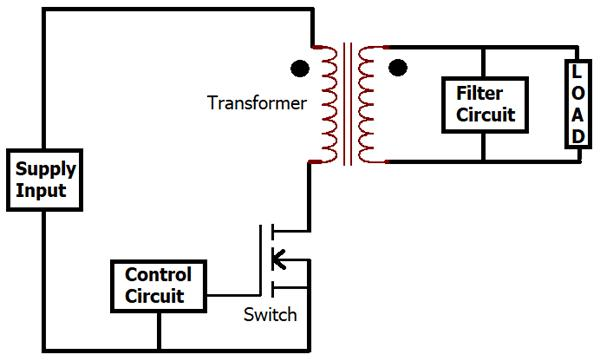
Its popularity comes from the fact that it combines transformer isolation and voltage conversion into a relatively simple structure. Unlike a conventional transformer that transfers energy continuously, the Flyback transformer stores energy during the MOSFET ON period and releases it to the secondary side when the switch turns OFF.
That operating principle allows designers to build a complete isolated power supply with fewer magnetic components than many competing topologies. In production terms, fewer components often means lower assembly cost, faster sourcing, and improved scalability.
Modern Flyback converters have also improved significantly compared with older generations. Quasi-resonant control, valley switching, synchronous rectification, and better ferrite materials now allow efficient compact products that would have been difficult to achieve years ago.
| Typical Flyback Application | Power Range |
| USB chargers | 5W–65W |
| Smart home devices | 5W–30W |
| CCTV systems | 12W–60W |
| Industrial auxiliary rails | 15W–100W |
| Open-frame embedded PSU | 30W–150W |
For many commercial products, Flyback remains the shortest path from concept to mass production.
Where Does Flyback Begin to Show Its Limits?
No topology is perfect. Flyback designs become more challenging as power increases because peak current stress rises quickly. Transformer leakage energy becomes harder to manage, thermal performance becomes tighter, and EMI control usually requires more effort.
As output power climbs, designers may encounter:
Higher MOSFET stress during switching transitions, stronger output ripple current, greater snubber loss, hotter magnetics, and reduced efficiency under continuous heavy load.
This does not mean Flyback cannot be used above 100W. Many modern designs do exactly that. But it often requires more advanced engineering, tighter transformer control, stronger thermal management, and higher-quality components.
That is why many engineers begin comparing Forward topologies once continuous power requirements move upward.
Why Does the Forward Converter Offer Better Efficiency?
The Forward converter differs from Flyback in one critical way: it transfers energy directly to the load while the primary switch is ON. Energy is not first stored entirely in the transformer gap and then released later.
This changes the electrical stress profile of the whole converter. RMS current can be lower, output filtering is often easier, and conversion efficiency is typically better in medium-power systems.
Forward converters are therefore common in industrial and infrastructure products where the load may run continuously for long periods. A system operating 24 hours per day benefits significantly from even a few percentage points of extra efficiency.
That efficiency gain reduces heat, improves capacitor life, lowers enclosure temperature, and sometimes allows smaller cooling structures.
| Parameter | Flyback | Forward |
| Typical Efficiency | Moderate | Higher |
| Ripple Current | Higher | Lower |
| Thermal Margin at Heavy Load | Moderate | Better |
| Complexity | Lower | Higher |
| Best Power Range | Low to Medium | Medium |
When reliability under continuous duty matters, Forward designs are often the stronger engineering decision.
Why Isn’t Forward Used Everywhere?
If Forward is more efficient, why not always choose it?
Because engineering decisions are rarely based on efficiency alone.
Forward converters typically require additional output inductors, reset circuitry, or more complex switch arrangements depending on architecture. Magnetics may become more specialized. PCB layout may be less forgiving than entry-level Flyback designs. The total component count is usually higher.
For low-cost consumer products, those extra parts may not be justified. For premium industrial products, they often are.
This is why topology choice should always be based on application priorities rather than theoretical superiority.
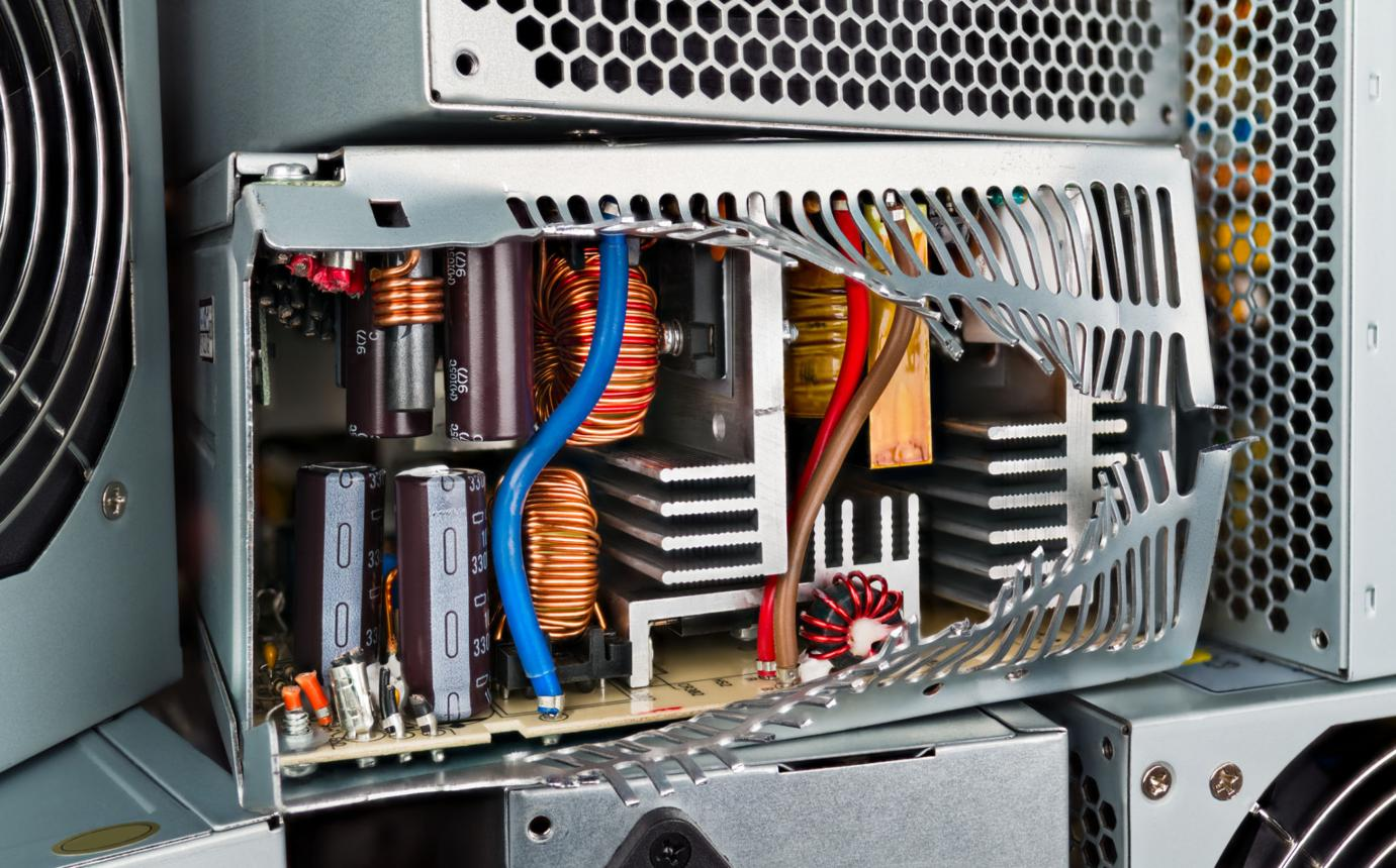
Why Is Transformer Design Often the Real Difference Between Good and Bad Power Supplies?
Many discussions about power supplies focus on controller ICs or MOSFET brands. In real manufacturing, transformer quality often determines whether a design becomes a stable product or a recurring service issue.
A transformer directly influences switching loss, leakage inductance, temperature rise, audible noise, regulation, insulation margin, surge survival, and EMI behavior. Two power supplies using the same schematic can perform very differently if the magnetics are different.
At SIPURUI, transformer development is treated as a core engineering stage rather than a purchasing afterthought. This is especially important in OEM projects where enclosure size, connector orientation, thermal path, and certification creepage distances are all constrained.
Typical core choices include EE, PQ, ETD, RM, and shielded pot structures. The best selection depends on power level, available volume, EMI targets, and production economics.
| Core Type | Common Benefit | Typical Use |
| EE / EI | Economical | General AC-DC |
| PQ | Compact + efficient | Industrial compact PSU |
| ETD | Better power density | 100W+ systems |
| RM | Low leakage | Precision electronics |
| Pot Core | Better shielding | Noise-sensitive products |
A well-designed transformer often saves more cost than chasing cheaper semiconductors later.

Why Does Leakage Inductance Cause So Many Problems?
Leakage inductance is one of the most underestimated causes of switching stress and EMI.
In simple terms, not all magnetic energy couples perfectly between windings. The uncoupled portion stores energy that must go somewhere when the switch turns OFF. That energy often appears as a voltage spike at the MOSFET drain.
If unmanaged, this can shorten transistor life, create radiated noise, and reduce efficiency.
That is why clamp or snubber networks are essential in many Flyback designs. Even when the converter appears electrically functional, poor leakage control can lead to field failures months later.
Good winding arrangement, layer structure, insulation thickness, and interleaving methods can reduce leakage dramatically before snubber parts are even selected.

Why Is EMI Still One of the Biggest Causes of Delay?
Many new products power up successfully on the first prototype. Far fewer pass EMC testing on the first attempt.
EMI failures are expensive because they consume lab time, engineering time, and schedule margin. In many projects, EMI—not basic functionality—is what delays shipment.
The main reason is that EMI is not caused only by the schematic. It is also created by geometry: current loop area, switching edge speed, parasitic capacitance, grounding path quality, cable behavior, heatsink coupling, and transformer structure.
That is why a design copied from a reference circuit may still fail badly if the layout is poor.
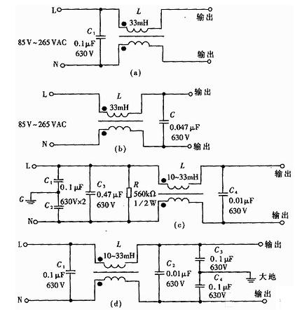
What Does a Practical EMI Input Filter Look Like?
Most offline switching power supplies use a front-end filter that combines surge handling and conducted noise suppression. Typical structures include fuse protection, MOV surge absorption, NTC inrush limiting, X capacitors, common-mode chokes, and Y capacitors.
These components must be selected as a system rather than individually. Oversizing capacitance may improve noise but worsen leakage current. Aggressive common-mode chokes may help one band while saturating under surge or load transients.
| EMI Component | Typical Function |
| X Capacitor | Differential noise suppression |
| Common Mode Choke | Common mode attenuation |
| Y Capacitor | Return path for HF noise |
| MOV | Surge protection |
| NTC | Inrush limiting |
Real success comes from tuning these parts together with PCB layout and transformer parasitics.
How Important Is PCB Layout Compared With Circuit Design?
Extremely important.
A technically correct schematic can still become a poor product if layout is careless. In many switching power supplies, the highest-noise loops should be treated almost like RF structures.
The path containing bulk capacitor, switch device, transformer primary, and return current should be kept compact. Gate drive loops should be short and clean. Sensitive feedback networks should stay away from high dv/dt nodes. Y capacitors should connect through the shortest practical path.
Good layout can improve EMI more than changing three generations of controller ICs.
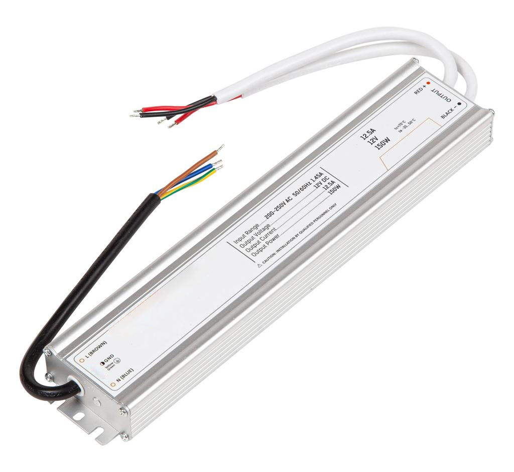
SIPURUI 5V 2A Compact Flyback Platform
A common customer request is a universal-input compact supply for networking or embedded products. In this range, a quasi-resonant Flyback platform remains highly competitive.
Typical specification:
- Input: 85–265VAC
- Output: 5V / 2A
- Efficiency: above 82%
- Isolation: 3kVAC
- Cooling: natural convection
- Compact enclosed or open-frame options available
For this category, the priority is usually size, cost control, standby performance, and fast customization.
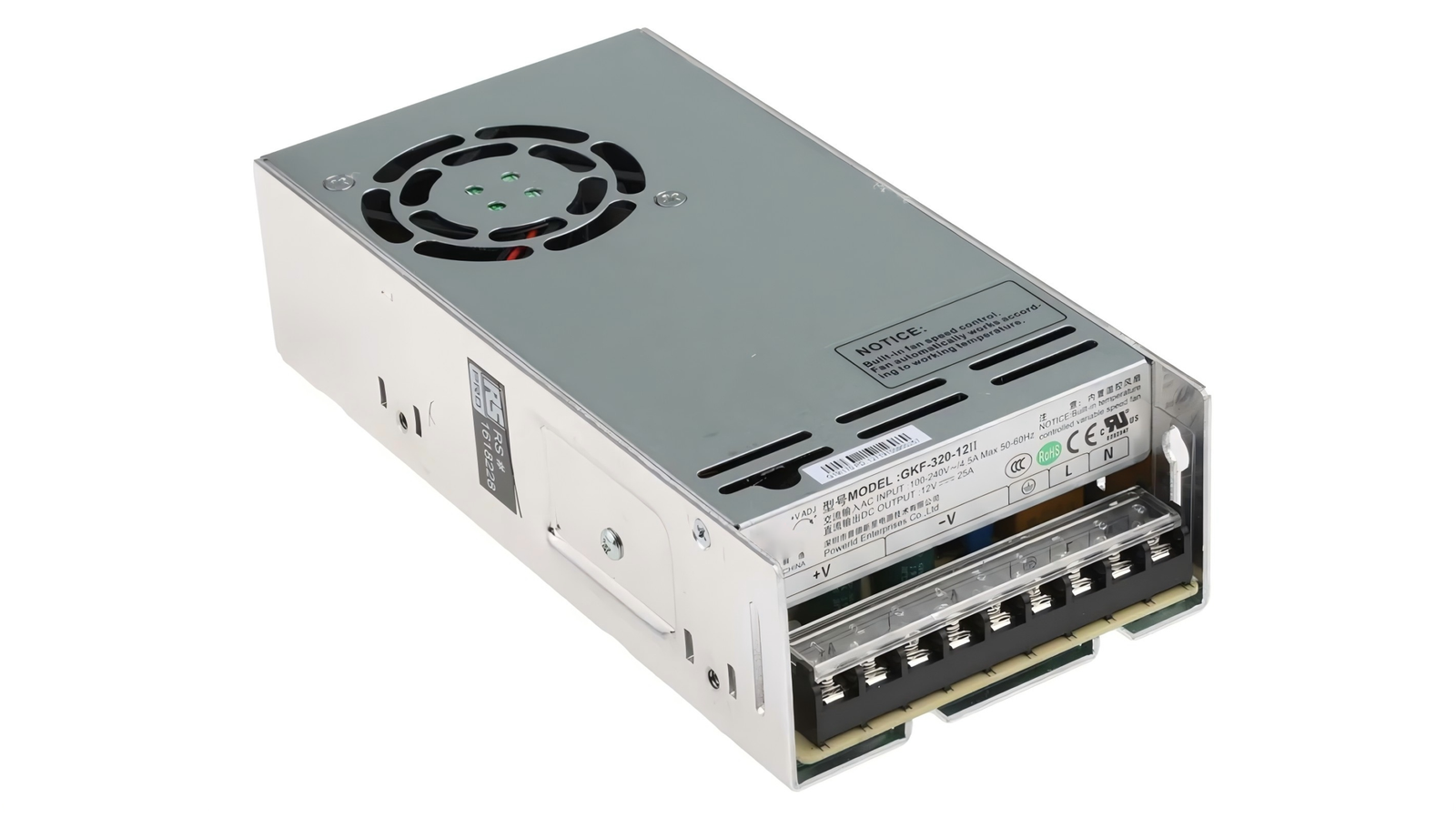
Example: SIPURUI 24V Industrial Forward Power Supply
For automation customers needing 24V rails under continuous load, Forward architecture is often preferred.
Typical specification:
- Input: 90–264VAC
- Output: 24V / 6A
- Efficiency: above 90%
- Full-load continuous operation
- OVP, OCP, OTP protection
- Industrial temperature options available
This type of platform is widely used in cabinets, PLC systems, actuators, access control, and factory electronics.
What Trends Are Defining Power Supply Design in 2026?
Customers now expect more from every watt.
They want smaller housings, lower no-load loss, wider input ranges, stronger surge tolerance, quieter EMI behavior, and longer capacitor life. At the same time, they still demand aggressive pricing.
This means manufacturers must optimize topology choice earlier in the project. Overdesign wastes money. Underdesign creates warranty risk.
The best modern suppliers are not those who simply quote a catalog model. They are the ones who understand how topology, magnetics, compliance, and manufacturing interact.

Final Conclusion: Which Topology Should You Choose?
Choose Flyback when product cost, compactness, and simplicity are the priority. It remains one of the most practical solutions for low-to-medium power isolated systems and continues to improve with modern control methods.
Choose Forward when efficiency, thermal margin, and continuous industrial duty matter more than the lowest BOM count. It is often the smarter long-term platform for heavier workloads.
In both cases, the real outcome depends on transformer quality, EMI engineering, thermal design, and manufacturing discipline.
At SIPURUI, we help OEM and industrial customers develop reliable custom switching power supplies based on real application needs rather than one-size-fits-all designs. Whether the right answer is Flyback or Forward, selecting the correct architecture early can save months of redesign and years of service issues later.