Understand how rectification, power factor correction, and isolated DC/DC conversion shape the safety, efficiency, power quality, and reliability of industrial AC/DC power supplies.
Overview
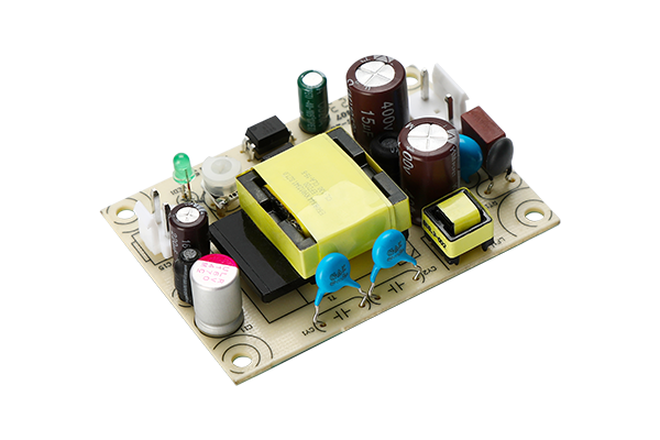
An industrial AC/DC power supply has a deceptively simple job: accept the mains and deliver regulated DC that a control system, motor drive, LED load, or electronic assembly can use. Inside the enclosure, however, the energy passes through several distinct electrical environments. The front end must tolerate line disturbances. The input current must meet power-quality limits. The high-voltage DC bus then has to be converted, isolated where the safety architecture requires it, and regulated at the output.
For most offline switch-mode power supplies, that journey can be understood in three stages: rectification, power factor correction (PFC), and isolated DC/DC conversion. The exact circuit varies with output power, input range, hold-up requirement, safety class, efficiency target, and cost. Knowing what each stage does makes datasheets easier to compare and helps buyers ask better questions during supplier qualification.

Stage 1: rectification creates a DC bus
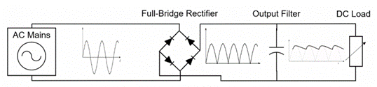
Mains voltage reverses polarity every half-cycle. The downstream switching stage needs a unidirectional supply, so the first power-processing block is normally a rectifier.
A half-wave rectifier uses one diode and passes only one half of the AC waveform. It is useful for illustrating the principle, but it makes poor use of the line cycle and produces heavy ripple. Commercial offline supplies normally use a four-diode full-wave bridge. During each half-cycle, a different diode pair conducts, so current at the bridge output always has the same polarity.
The bridge output is pulsating DC, not a steady rail. A bulk capacitor charges near the peaks of the rectified waveform and supplies energy between peaks. At 50 Hz mains, full-wave rectification produces a 100 Hz ripple component; at 60 Hz, the corresponding ripple is 120 Hz. Capacitor value, load current, permitted bus ripple, hold-up time, inrush current, lifetime, and ambient temperature all enter the design decision.
For a 230 V RMS input, the ideal peak is about 325 V before diode drops and loading. That number is often rounded to 320-325 V in design discussions. It is not a regulated value: the bus changes with line voltage, load, ripple, and component losses.
Why the capacitor causes narrow current pulses
The bulk capacitor draws current only when the instantaneous rectified line voltage rises above the capacitor voltage by enough to forward-bias the bridge. Instead of following the sine wave, input current arrives in short pulses near the voltage peaks. Those pulses increase RMS current in the cable, fuse, bridge, EMI filter, and upstream distribution system. They also create harmonic current.
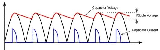
This behavior explains why a power supply can have acceptable real-power efficiency yet a poor power factor. Efficiency describes how much input power reaches the load. Power factor describes how effectively the supply draws current from the AC source. They are related in system design, but they are not interchangeable specifications.
Diode bridges versus active rectification
A conventional bridge places two diode drops in the current path at any instant. At modest power, its low cost and simple control are hard to beat. As current rises, conduction loss and heat become more important. Active bridge or bridgeless rectifier arrangements replace some or all of the diode conduction path with controlled MOSFETs. A modern example is the totem-pole PFC front end.
Active rectification is not a free efficiency upgrade. Reverse-recovery behavior, dead time, common-mode noise, start-up, surge survival, and fault handling need careful engineering. Wide-bandgap switches such as GaN and SiC can improve high-frequency performance, but the controller and magnetic design must justify their cost.
| Front-end option | Main advantage | Main tradeoff | Typical fit |
|---|---|---|---|
| Diode bridge plus bulk capacitor | Low cost and simple control | High harmonic current and bridge conduction loss | Low-power or cost-led supplies where compliance allows |
| Diode bridge plus boost PFC | Mature architecture with controlled input current | Two bridge diode drops remain in the power path | Industrial supplies across a broad mid-power range |
| Bridgeless or totem-pole PFC | Lower conduction loss and high power-density potential | More demanding control, protection, and EMI design | High-efficiency, higher-power, or compact premium designs |
Stage 2: PFC controls how the supply loads the grid
Power factor correction changes the input-current waveform so it more closely follows the line voltage. In a well-designed active PFC stage, the current is approximately sinusoidal and in phase with the voltage. The result is a higher true power factor and lower low-order harmonic current than a simple bridge-and-capacitor input.
Passive PFC uses line-frequency inductors and capacitors. It is simple and can improve the waveform, but the magnetics become bulky as power rises, and performance is limited across a wide input and load range.
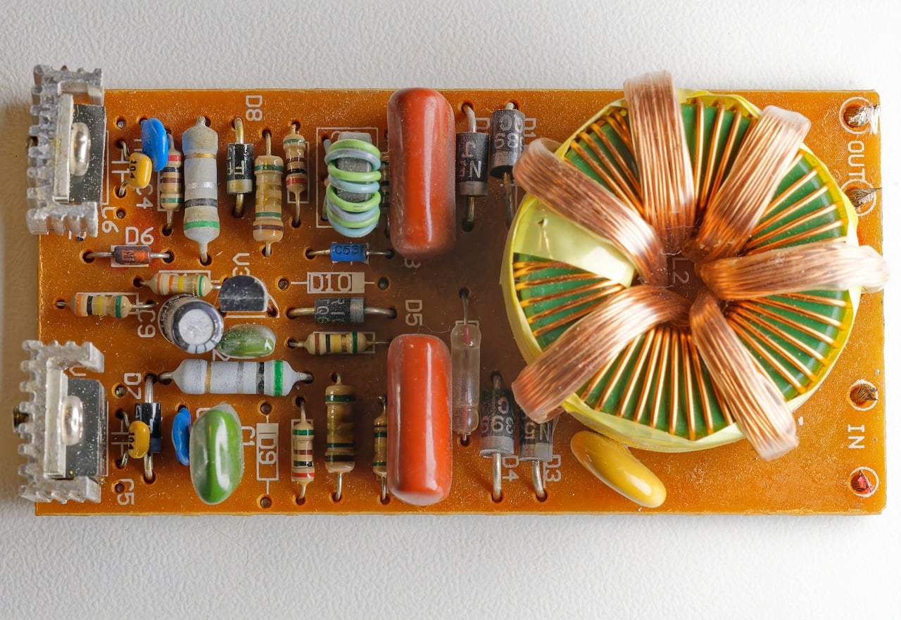
Active PFC normally uses a controlled switching converter. The classic implementation is a boost stage placed after the bridge rectifier. A controller senses line voltage, bus voltage, and switch or inductor current, then adjusts duty cycle so the input current follows a reference derived from the rectified line. The stage also regulates a DC link commonly around 380-400 V in universal-input designs, although the exact setpoint belongs to the product design.
The boost switch operates at a much higher frequency than the mains. That makes the inductor and filter components smaller, but it also introduces switching ripple that the EMI filter must attenuate. The useful distinction is this: PFC suppresses the problematic low-order line harmonics by shaping the average input current; the switching ripple is handled separately through topology choice, layout, and filtering.
When is PFC required?
There is no universal wattage at which every product suddenly requires the same circuit. Requirements depend on equipment class, rated input power, market, and the edition of the applicable standard. IEC 61000-3-2 is the common reference for harmonic-current limits on equipment with input current up to 16 A per phase. Many industrial designs above roughly 75 W include active PFC, but engineers should verify the product classification and regional compliance plan rather than treating 75 W as a global design law.
PFC also affects procurement. A datasheet that lists only “PF > 0.95” is incomplete without the input voltage, load point, and test conditions. For variable-load equipment, performance at 20%, 50%, and full load may matter more than a single best-case number. Current total harmonic distortion (THD), efficiency, no-load consumption, and conducted-emissions results complete the picture.
| Buyer question | Why it matters | Evidence to request |
|---|---|---|
| At what line and load is power factor specified? | PF usually falls at light load and may vary across the input range | Test curves for low line, high line, and several load points |
| Which harmonic-current class applies? | Compliance limits depend on equipment classification | IEC 61000-3-2 test report and declared product class |
| How is surge and inrush handled? | The PFC bus and bulk capacitor see high electrical stress | Inrush limit, surge test level, protection schematic summary |
| What is the PFC switching mode? | CCM, CrM, interleaved, and totem-pole designs have different loss and EMI profiles | Topology description, efficiency curve, thermal data |

Stage 3: isolated DC/DC conversion sets the output and safety boundary
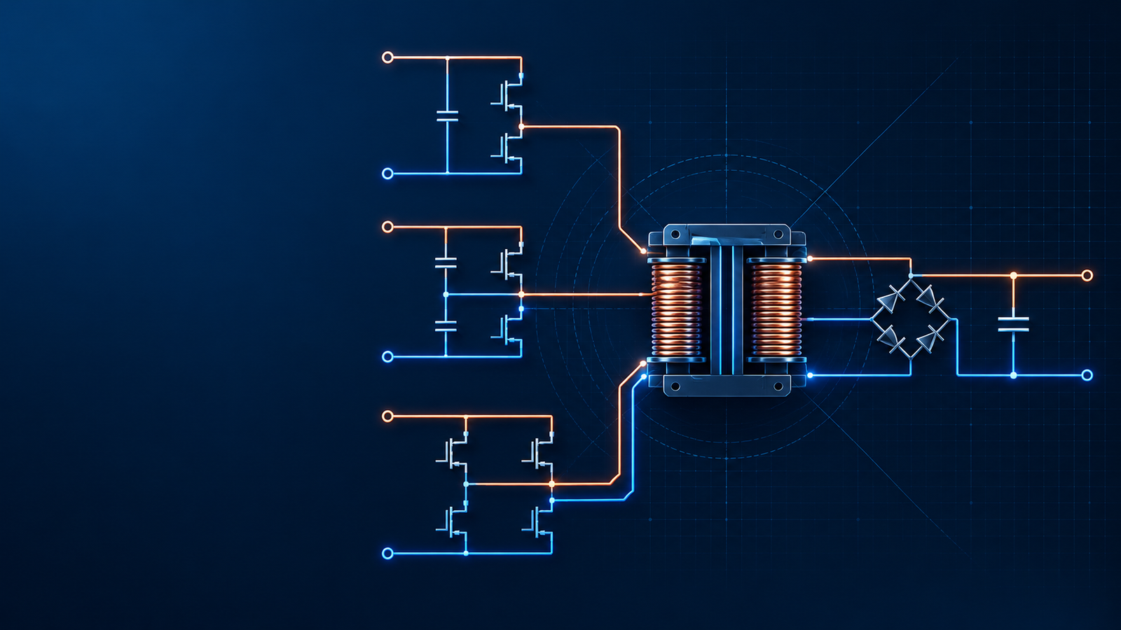
After rectification and optional PFC, the supply has a high-voltage DC bus. The next stage switches that bus at high frequency, transfers energy through magnetics, rectifies it on the secondary side, and closes a feedback loop around the output.
Galvanic isolation separates conductive paths between the mains side and the user-accessible or load side. The transformer provides the energy-transfer barrier, but the safety result depends on the whole construction: creepage, clearance, insulation system, transformer design, PCB slots, optocoupler or isolated-feedback path, Y capacitors, enclosure, earthing, and production testing.
Isolation is common in industrial AC/DC supplies because it supports SELV or other protected low-voltage outputs and simplifies the safety boundary seen by connected equipment. It is not automatically required in every internal power-conversion function. A non-isolated offline buck can be valid inside a sealed product where the output remains hazardous and inaccessible. It is a poor substitute when field wiring or users may touch the output.
Flyback conversion: economical and flexible
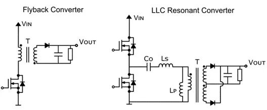
The flyback is widely used at lower power because it combines energy storage, voltage conversion, and isolation with a modest component count. When the primary switch turns on, energy is stored in the coupled magnetic element. When the switch turns off, that energy moves to the secondary and the output capacitor.
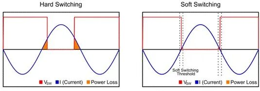
Traditional hard-switched flyback designs can suffer turn-on and turn-off loss, transformer leakage-energy spikes, and EMI. Quasi-resonant, valley-switching, active-clamp, and hybrid-flyback methods extend useful power and efficiency well beyond what a simple fixed-frequency example suggests. For that reason, “flyback below 100 W” is a handy teaching shortcut, not a firm boundary. Output voltage, input range, thermal environment, size, switching devices, and required efficiency can move the practical crossover substantially.
LLC conversion: soft switching for higher power density
An LLC stage uses a resonant capacitor, resonant inductance, and transformer magnetizing inductance. The controller regulates output by changing switching frequency relative to the resonant network. When designed and operated in the intended region, the primary MOSFETs can turn on with near-zero voltage, while the secondary current can commutate with low current. Lower switching loss makes high frequency and high power density more practical.
LLC is attractive for higher-power supplies with a relatively controlled DC link and output range. It is less forgiving when the design must regulate across an extremely wide gain range. Resonant-tank tolerances, burst-mode behavior, synchronous-rectifier timing, and light-load control deserve as much attention as the headline full-load efficiency.
| Design factor | Flyback family | LLC resonant family |
|---|---|---|
| Component count | Usually lower | Higher; resonant tank and half- or full-bridge drive required |
| Best operating range | Strong fit for lower power and wide input/output requirements | Strong fit for higher efficiency and power density around a defined operating window |
| Switching behavior | Hard switching in basic versions; QR and active-clamp variants reduce loss | Soft-switching operation is central to the topology |
| Control and magnetics | Relatively accessible, though leakage spikes need attention | Resonant design and frequency control are more demanding |
| Procurement focus | Peak switch stress, transformer temperature, snubber loss, standby power | Tank tolerance, ZVS range, light-load behavior, synchronous rectification |
How the three stages affect the final product
The stages cannot be optimized independently. A higher PFC bus voltage can reduce current in the isolated stage, but it increases voltage stress and influences hold-up energy. Raising switching frequency shrinks magnetics, yet switching and core losses rise unless topology, devices, and layout support the change. A low-loss front end can improve enclosure temperature, which in turn increases electrolytic-capacitor life.
For B2B buyers, topology names are useful only when tied to measured performance. Compare efficiency across the actual input and load range. Check power factor and THD at realistic operating points. Review isolation rating together with creepage, hipot test conditions, safety approvals, and leakage current. Ask for thermal data at the required ambient temperature and mounting orientation. A supply that reaches 94% on an open bench at room temperature may behave differently inside a sealed control cabinet at 50°C.
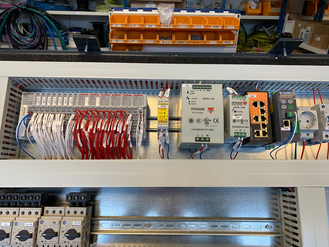
The same discipline applies to reliability. The bridge rectifier, bulk capacitor, PFC switch, transformer, and secondary rectifier each create heat. Component temperature, not the ambient number alone, drives wear-out. Derating data and a credible thermal report are usually more informative than an isolated MTBF claim.
Final selection checklist
| Area | Confirm before approval |
|---|---|
| AC input | Voltage and frequency range, inrush, surge immunity, fuse strategy, brownout behavior |
| Power quality | PF and THD conditions, applicable IEC 61000-3-2 class, light-load behavior |
| Isolation and safety | Isolation class, creepage and clearance, hipot test, leakage current, approvals |
| DC output | Regulation, ripple and noise, transient response, hold-up time, protection modes |
| Thermal and lifetime | Efficiency map, component temperatures, derating curve, capacitor lifetime basis |
| Manufacturing evidence | Production hipot/ground-bond tests, traceability, change control, reliability screening |
Conclusion
Rectification builds the high-voltage DC bus. PFC controls the way energy is drawn from the mains. The isolated DC/DC stage then delivers the required voltage while establishing the safety boundary and much of the supply's efficiency, size, and thermal behavior.
There is no single best circuit for every product. A simple diode bridge and flyback may be the right answer for a compact low-power controller. A high-density industrial supply may justify totem-pole PFC, an LLC stage, and synchronous rectification. The sound choice is the one that meets the complete operating envelope and is supported by compliance and thermal evidence.
SIPURUI can support OEM and automation projects with AC/DC power-supply selection based on input range, output requirements, cabinet conditions, safety expectations, and production volume. Share the load profile and installation constraints to begin with an engineering fit rather than a catalog-only match.