A 300 W switching power supply may draw only a few amperes in normal operation, yet pull several tens of amperes for a few milliseconds when AC power is first applied. Learn what creates inrush current, what it can damage, and how to control it safely.
A 300 W switching power supply may draw only a few amperes in normal operation, yet pull several tens of amperes for a few milliseconds when AC power is first applied. That brief pulse is inrush current. It is a normal consequence of charging the high-voltage DC bus, but it can still open a fuse, stress a bridge rectifier, pit a relay contact, or trip an upstream circuit breaker.
For an equipment designer, the useful question is not whether inrush exists. It is whether the power supply, protection devices, wiring, and system-level startup sequence can tolerate the magnitude, duration, and repetition rate of the pulse. This article explains what creates the current, why some installations suffer more than others, and how to select a control method without creating a new thermal or reliability problem.
What Inrush Current Means in an AC-DC Power Supply
Inrush current is the short-duration input-current peak that occurs when an unenergized AC-DC supply is connected to the mains. It is different from steady-state input current and from the repetitive current pulses drawn by a conventional bridge-and-capacitor input during normal operation.
At 230 V AC, the sine-wave peak is approximately 325 V, not 230 V. In a basic offline supply, the bridge rectifier connects that waveform to a discharged bulk capacitor. At the instant of connection, the capacitor voltage is near zero and its effective impedance is very low. The initial current is therefore limited mainly by the source impedance, wiring, bridge resistance, capacitor equivalent series resistance, and any intentional inrush-limiting component.
A first-order view is:
Initial charging current is approximately the instantaneous line voltage divided by the total series impedance.
This is not a complete design equation because the rectifier conducts nonlinearly and the voltage changes during charging. It is still a useful way to understand why a stiff supply line, a large capacitor, and little series resistance create a high peak.
The Main Cause: Charging the Input Bulk Capacitor
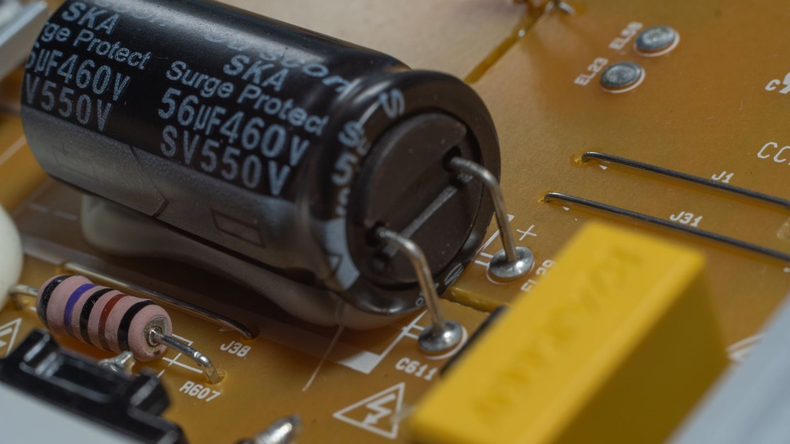
The input electrolytic capacitor must store enough energy to support the converter between rectified line peaks and during short mains disturbances. Before startup, however, it is discharged. When the AC switch closes, the capacitor initially behaves almost like a short circuit.
Three variables dominate the event:
Capacitance and stored energy. A larger capacitor normally requires more charge and increases the energy that the limiting circuit must absorb. Peak current does not scale with capacitance alone, but pulse duration and total stress usually rise as capacitance increases.
Switching phase. Closing near the AC voltage peak produces a much larger first pulse than closing near a zero crossing. Mechanical switches and contactors normally close at an uncontrolled phase, so qualification must consider the worst credible point on the waveform.
Total source impedance. Short, heavy wiring and a low-impedance utility feed reduce natural current limiting. A supply that behaves well on a laboratory extension lead can show a higher peak beside a distribution panel.
The capacitor is therefore the primary source of inrush in most small and medium offline switching supplies. The high-frequency transformer is usually not the main contributor because it is not connected directly across the mains at turn-on and the controller normally manages switching startup.

How PFC Changes the Startup Event
Power-factor-corrected supplies often use a boosted DC bus around 380 to 400 V and a substantial energy-storage capacitor. Before the PFC controller begins normal regulation, that capacitor needs a precharge path, commonly through the bridge and a diode or through a designed limiting network.
It is tempting to state that every PFC supply has more inrush than a non-PFC flyback supply. That is too broad. A higher-power PFC unit may have a larger energy store, but its actual inrush depends on its bulk capacitance, passive or active precharge, controller sequence, input impedance, and specified test conditions. A well-designed PFC front end with controlled precharge can produce less system trouble than a smaller supply with a poorly selected NTC.
The PFC inductor may carry transient current as the converter starts, but the first large AC-input pulse is still normally associated with charging the DC bus. PFC soft-start should prevent the control loop from commanding an abrupt boost event. If a second current step appears when PFC begins switching, the designer should examine the controller sequence and current limit rather than treating it as unavoidable transformer magnetizing inrush.
| Startup contributor | Typical importance in an SMPS | What increases it | Practical observation |
|---|---|---|---|
| Input bulk-capacitor charging | Dominant | Larger energy storage, high line, low source impedance | One or several sharp pulses immediately after connection |
| PFC bus precharge and takeover | Moderate to high in PFC supplies | Large bus capacitor, weak precharge, poor startup sequencing | Initial charging pulse, sometimes followed by a controller-start transient |
| High-frequency transformer magnetizing current | Usually secondary | Abnormal drive, flux imbalance, failed soft-start | More often a design or fault symptom than the primary mains inrush source |
| EMI-filter capacitors | Usually small | Large X-capacitance, high line | Very short displacement-current component |
Why Hot Restarts Are a Special Problem
An NTC thermistor is popular because it is simple. Its cold resistance limits the first charging pulse. Load current then heats it, causing its resistance to fall and reducing steady-state loss.
The same behavior creates a weakness. If power is removed and restored before the NTC cools, its resistance remains low. The DC bus may discharge faster than the thermistor recovers, leaving a discharged capacitor behind an ineffective limiter. TDK notes that full NTC recovery can take roughly 30 to 120 seconds depending on the device and installation.
This explains a common service pattern: a product starts reliably from cold but blows a fuse or trips a breaker when an operator cycles power quickly. Short utility interruptions and automatic restart sequences can reproduce the same condition.
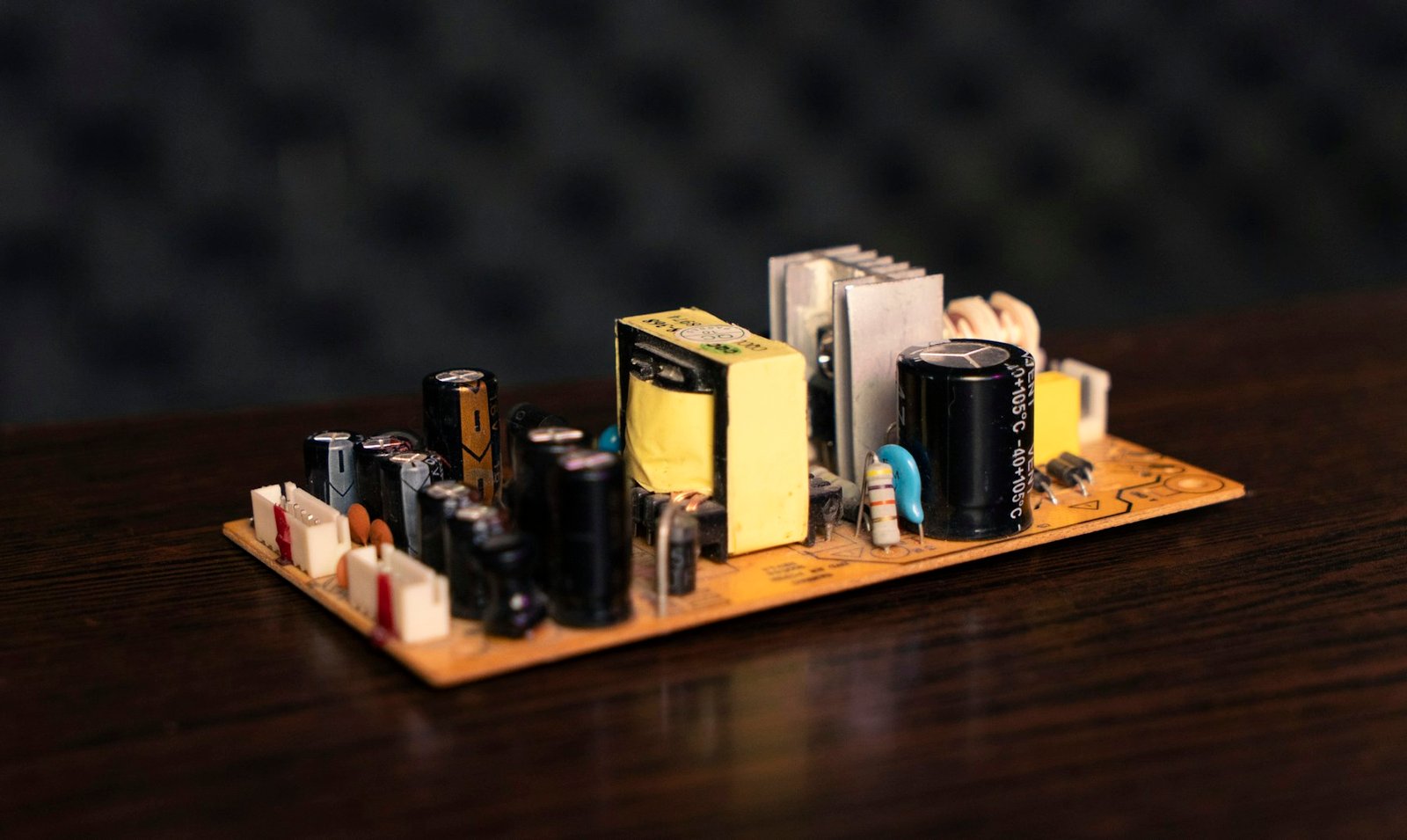
External Conditions That Magnify Inrush
The power supply is only one part of the current path. Installation details often decide whether the pulse is harmless or disruptive.
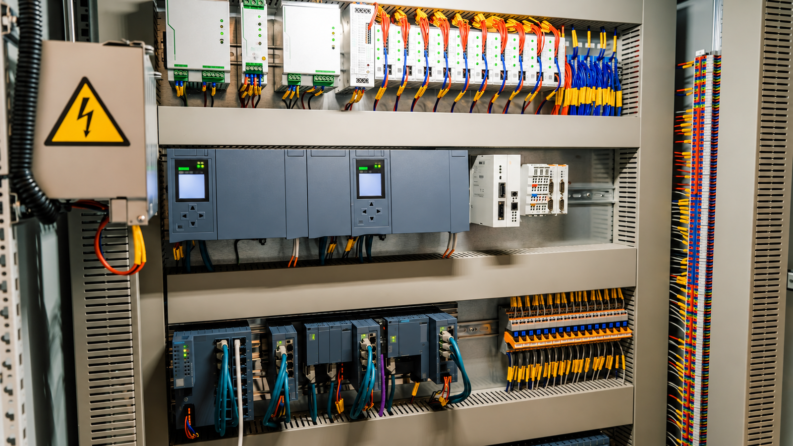
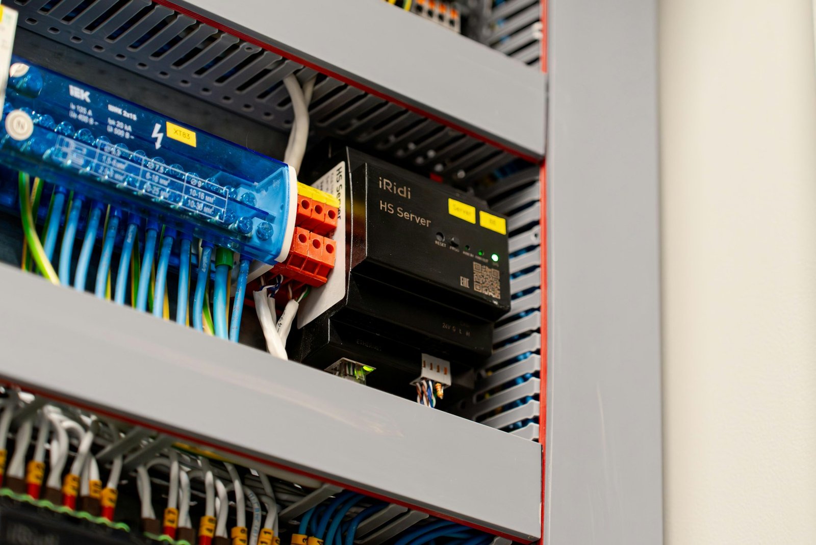
Multiple supplies starting together. Ten DIN-rail supplies connected behind one contactor can create approximately coincident charging pulses. Their peaks will not always add perfectly because wiring impedance and individual conduction timing spread the event, but assuming that nameplate running currents are the only concern is unsafe.
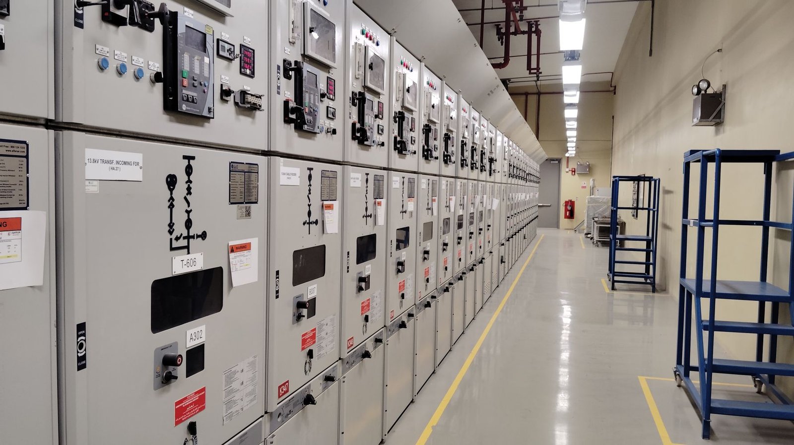
A stiff upstream source. Low-impedance transformers, short conductors, and high fault-current distribution systems allow a higher peak than weak or long branch circuits.
High line and elevated temperature. High line increases the available charging voltage. High ambient temperature lowers the initial resistance of an NTC, reducing its limiting effect before startup.
Protection-device characteristics. A breaker responds to both current magnitude and time. Two breakers with the same nominal ampere rating may behave differently because their instantaneous trip curves differ. A time-delay fuse may ride through a pulse that opens a fast-acting fuse of the same current rating.
Input Inrush Is Not Output Capacitive Startup Current
These two events are often confused during troubleshooting.
| Characteristic | AC input inrush | Output capacitive startup current |
|---|---|---|
| Location | Mains input and high-voltage DC bus | Low-voltage output |
| Main cause | Charging the rectified-line bulk capacitor | Charging external load capacitance |
| Typical symptom | Fuse opens, bridge stress, contact arcing, breaker trip | Output ramps slowly, current limit, hiccup mode, failure to start |
| Main protection concern | Fuse, bridge rectifier, NTC or precharge switch, upstream breaker | Output rectifier or synchronous FETs, control loop, current-limit circuit |
| Typical remedy | Input precharge or inrush limiter | Controlled output ramp, capacitance limit, load sequencing |
An oscilloscope measurement at the AC input distinguishes the two. If the input pulse is acceptable but the output repeatedly rises and collapses, the likely issue is output overload or excessive load capacitance rather than AC inrush.
What Inrush Current Can Damage
The pulse is brief, but repeated stress accumulates. Bridge-rectifier surge-current ratings, capacitor ripple and surge capability, fuse pre-arcing I²t, relay contact rating, PCB trace current density, and NTC energy rating all matter.
Field symptoms include nuisance breaker trips, occasional fuse failures during cold start, more frequent failures during hot restart, discolored NTC devices, welded or pitted switch contacts, and resets of equipment sharing the same AC branch. A current spike can also create conducted disturbance through common wiring, although it should not be confused with a standardized surge-immunity event such as IEC 61000-4-5.
Practical Inrush-Limiting Methods
NTC thermistor
An NTC is economical and effective in supplies that start infrequently and operate within a controlled temperature range. Selection must account for cold resistance, maximum continuous current, maximum permitted capacitance or pulse energy, ambient derating, physical spacing, and cooldown time. Parallel NTCs are generally a poor choice because current sharing becomes unstable as the warmer part drops in resistance.
Fixed resistor with relay or triac bypass
A precharge resistor limits the capacitor current, then a relay or semiconductor bypasses it after the bus reaches a safe voltage. This approach reduces steady-state loss and can be designed for predictable restart behavior. The control logic must prevent premature bypass and must handle a relay or drive failure safely.
NTC with bypass
Combining an NTC with a delayed bypass is common in higher-power industrial supplies. The NTC provides simple initial limiting, while the bypass eliminates most running loss. The design still needs a defined response to rapid power cycling; timing alone is weaker than confirming that the DC bus has actually charged.
Active inrush limiting
MOSFET-based or thyristor-based circuits can shape the charging current and support frequent starts. They offer better control but add components, heat, control-power requirements, and failure modes. They are most attractive when startup repetition, efficiency, size, or breaker coordination makes passive limiting inadequate.
Zero-cross switching and sequenced startup
Connecting near a voltage zero crossing can reduce the first charging step, but zero-cross switching alone does not remove the need to manage capacitor energy. In multi-supply systems, staggered enable signals or contactors can be more effective because they prevent several independent pulses from coinciding.
| Application condition | Usually suitable approach | Design check that is easy to miss |
|---|---|---|
| Small supply, infrequent cold starts | Series NTC | High-temperature start and minimum cooldown time |
| Medium or high power, long run time | Resistor or NTC with relay bypass | Bypass only after adequate bus precharge |
| Frequent cycling or automatic restart | Active precharge or controlled bypass | Safe behavior at every off-time, including partial bus discharge |
| Many supplies on one branch | Staggered startup plus per-unit limiting | Worst-case simultaneous command and breaker instantaneous curve |
| Wide ambient-temperature range | Active solution or carefully qualified thermistor network | NTC resistance at both hot and cold extremes |
How to Measure and Specify Inrush Correctly
An inrush number without test conditions is incomplete. A procurement or engineering specification should state the input voltage, AC phase or worst-case method, source impedance, ambient temperature, initial bus condition, off-time before restart, and the measurement bandwidth or current-probe method.
Test at high line and repeat enough starts to capture phase variation. Measure both cold start and hot restart. For systems with several power supplies, test the assembled cabinet with the real contactor, wiring, breaker, and startup logic. Record peak current, pulse duration, and a waveform or I²t metric suitable for comparing against fuses and semiconductor ratings.
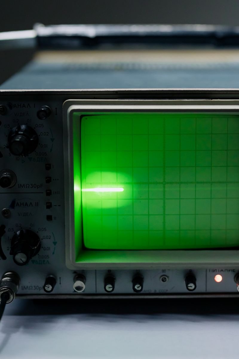
Do not place an oscilloscope ground clip directly on a live, non-isolated primary circuit. Use a rated current probe and appropriate differential or isolated measurement equipment, following the laboratory's high-voltage safety procedure.
A Buyer and System Integrator Checklist
Before approving a power supply, ask for more than a single maximum-ampere figure:
Is the stated inrush value measured at 115 V AC, 230 V AC, or both?
Does the datasheet distinguish cold start from warm or rapid restart?
What ambient temperature and source impedance were used?
How long is the pulse, and what is its I²t?
Is the limiter a passive NTC, a bypassed network, or an active circuit?
How many units may start on the same branch, and are their starts sequenced?
Has the specified fuse or breaker curve been checked against the measured waveform?
Does the supply recover cleanly after a short mains interruption?
These questions are especially important for automation cabinets, LED systems, telecom racks, test equipment, and machines where operators may cycle power repeatedly.
Conclusion
Switching power supply inrush current is a normal charging event, not evidence that the power supply is already damaged. The main source is the high-voltage input capacitor; PFC architecture, startup sequencing, NTC temperature, line impedance, and the number of supplies energized together determine how severe the event becomes.
The most reliable design process is to define real startup conditions, measure the waveform, coordinate the limiter with the fuse or breaker, and test cold starts as well as rapid restarts. SIPURUI can support OEM buyers with power-supply selection and application discussions where startup current, cabinet integration, and protection coordination are part of the requirement.