Compare push-pull, half-bridge, full-bridge, PSFB, and LLC choices by switch stress, transformer use, RMS current, gate drive, protection, and real application conditions.
Overview
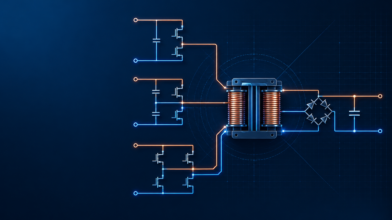
Push-pull, half-bridge, and full-bridge converters can all provide transformer isolation, voltage conversion, and high-frequency operation. That common description hides the decisions that make or break a real power supply. A 48 V battery converter and a 400 V PFC bus may deliver the same output power, yet they place very different voltage stress on the primary switches. A topology that looks cheaper on the schematic may demand a harder transformer build, more copper, or tighter protection.
The practical selection order is straightforward: establish the worst-case input bus, calculate switch stress including transient margin, check transformer volt-seconds, and then compare conduction loss, gate-drive complexity, protection, and production risk. Nominal wattage alone is a poor selector.
This guide compares conventional PWM versions of the three isolated topologies. Phase-shifted full bridge (PSFB) is covered separately because it uses the same bridge hardware but changes the switching behavior. LLC is mentioned only where it is a realistic alternative.
The short answer
For low-voltage battery or telecom inputs, push-pull remains attractive because both primary switches can use ground-referenced drives. The penalty is severe: each switch may see roughly twice the input voltage before leakage-inductance overshoot is added, and any mismatch between the two half-primary windings can drive the transformer toward saturation.
Half-bridge is often the economical choice on a high-voltage DC link when power is moderate. Each switch blocks approximately the bus voltage, and the transformer sees about half the bus amplitude. The reduced primary voltage means higher current for the same transferred power, so copper loss and transformer design become less favorable as power rises.
Full-bridge applies the full bus across an ordinary primary winding. It needs four active switches and two high-side drive channels, but it uses the bus more effectively and reduces primary current for a given power level. That trade usually becomes worthwhile at kilowatt-class power, especially when PSFB operation can reduce turn-on loss over the intended load range.
How the three power stages work
Push-pull
A push-pull converter uses a center-tapped primary. The DC input feeds the center tap, and two low-side switches alternately energize the two half-windings. The secondary therefore receives alternating polarity without a high-side primary switch.
This arrangement is simple to drive, but the transformer is less forgiving than the schematic suggests. The two half-primary windings need closely matched turns, coupling, and resistance. Gate timing and current limit must also behave symmetrically. When one half-cycle applies more volt-seconds than the other, flux walks in one direction until magnetizing current rises sharply.
The off-state switch stress is also decisive. In an idealized push-pull stage, the inactive device can see approximately 2 × Vin. Real hardware adds leakage-inductance overshoot and ringing. A 48 V system can therefore justify a 150 V device after the actual input tolerance, clamp level, and derating policy are considered. Applying the same topology to a 400 V bus would push the ideal stress toward 800 V before transients, which defeats its usual cost and drive advantages.
Half-bridge
A conventional half-bridge places two switches in series across the DC bus. The transformer primary connects between the switching node and the midpoint of two series bus capacitors. Each switch blocks roughly Vin, while the transformer is driven by approximately ±Vin/2.
The split capacitors help establish the midpoint and block sustained DC through the transformer path, but they do not make flux balance automatic under every transient and control condition. Capacitance tolerance, ESR, startup sequencing, asymmetric drive, and unequal loading can move the midpoint. Designers still need to verify capacitor ripple current, midpoint behavior, dead time, startup pulses, and the transformer current waveform.
Because the primary receives half the bus amplitude, a half-bridge normally needs about twice the primary current of a full bridge for the same power, turns ratio, duty conditions, and efficiency assumptions. That increases copper loss and may enlarge conductors or magnetic components. The attraction is a two-switch high-voltage power stage rather than a four-switch bridge.
Full-bridge
A full-bridge uses two legs and four switches. One diagonal pair applies +Vin to the primary; the other applies -Vin. Each device blocks approximately Vin, and the transformer receives the full bus amplitude. For a given transferred power, this generally produces the lowest primary current of the three arrangements discussed here.
The price is added hardware and more ways to fail. Both legs need controlled high-side and low-side drive. Dead time and interlock must prevent simultaneous conduction in either leg. Propagation-delay mismatch, common-mode transients, Miller turn-on, and gate-loop layout become part of the power-stage design rather than secondary details.

Side-by-side engineering comparison
| Design factor | Push-pull | Half-bridge | Full-bridge |
|---|---|---|---|
| Primary switches | 2 low-side devices | 2 devices in one leg | 4 devices in two legs |
| Idealized off-state stress | About 2 × Vin, plus overshoot | About Vin, plus overshoot | About Vin, plus overshoot |
| Primary voltage amplitude | Approximately Vin on each active half-primary | Approximately Vin/2 | Approximately Vin |
| Transformer primary | Center-tapped; halves must match | Single winding | Single winding |
| Gate drive | Two ground-referenced channels | One high-side and one low-side channel | Two high-side and two low-side channels |
| Flux-balance sensitivity | High | Lower when the midpoint network is well designed, but not zero | Requires volt-second balance; PSFB adds circulating-current considerations |
| Typical fit | Low-voltage isolated DC-DC | Moderate-power high-voltage DC link | Higher-power high-voltage DC link |
| Main design trap | Underestimating 2 × Vin stress and flux walk | Treating the capacitor midpoint and bootstrap supply as self-solving | Underestimating commutation, driver, layout, and protection complexity |
These are structural tendencies, not guaranteed power limits. Semiconductor technology, cooling, switching frequency, magnetic design, allowable ripple, isolation requirements, and production volume can move the practical boundary by a wide margin.
Five checks that should drive the selection
1. Calculate switch stress from the worst case, not the nominal bus
Start with maximum input voltage, not the label on the supply. Add the reflected or reset voltage imposed by the topology, leakage-inductance overshoot, control overshoot during startup or load release, and the company’s derating requirement. Confirm the result with a high-bandwidth differential probe and a low-inductance measurement loop on representative hardware.
The common shortcut “400 V bus means 600 V MOSFET” may be reasonable in one design and unsafe in another. A PFC output can rise above its nominal value, while PCB inductance and transformer leakage can produce fast drain spikes. Clamp design, device avalanche capability, temperature, and repetitive stress all matter.
For push-pull, the same discipline is even more important because the idealized starting point is already about 2 × Vin. Snubbers and clamps control energy that has already been created; they do not remove the topology’s basic voltage relationship.
2. Treat volt-second balance as a measured requirement
Transformer saturation is often discussed as a magnetic-component problem, but the root cause may sit in gate timing, current sensing, winding construction, or startup control. The useful test is whether positive and negative primary volt-seconds remain balanced across line, load, startup, shutdown, pulse skipping, and protection recovery.
Push-pull is particularly exposed because the two half-primary windings are separate physical structures. Full-bridge stages can also develop flux walk when diagonal conduction intervals or voltage drops differ. Peak-current-mode control, a series blocking capacitor, flux-balancing logic, and cycle-by-cycle current limit are possible remedies, but each has operating limits that must be checked.
In a half-bridge, the split capacitor network provides a DC-blocking mechanism and tends to restore midpoint balance. It still needs matched, correctly rated components and a startup sequence that does not leave one capacitor or the transformer with a damaging initial condition.
3. Compare RMS current and copper loss, not just switch count
At the same bus voltage, full-bridge applies twice the primary voltage of half-bridge. For comparable power transfer, the half-bridge primary current is correspondingly higher. That affects transformer wire area, copper loss, switch conduction loss, capacitor ripple current, connector heating, and PCB copper.
Push-pull uses the full input across one half-primary at a time, but only half of the center-tapped primary carries current during each interval. The extra copper and the need for tightly matched halves can offset some of the apparent simplicity.
This is why BOM comparisons should be made at the assembled converter level. Four switches may cost more than two, yet a full bridge can reduce current rating, copper area, thermal burden, or magnetic size enough to recover part of that difference.
4. Audit the gate-drive power supply and timing
Push-pull usually wins on drive simplicity because both switches are referenced to primary ground. Half-bridge and full-bridge require high-side drive, implemented with isolated bias supplies, pulse transformers, level shifters, or bootstrap circuits.
Bootstrap behavior is sometimes reduced to an inaccurate rule about “50% duty cycle.” The actual constraint is refresh time: the switch node must return low often and long enough to recharge the bootstrap capacitor, while quiescent current, gate charge, leakage, switching frequency, and startup conditions determine how quickly the stored charge falls. A conventional symmetric half-bridge often has enough low-side time in steady state. Problems appear during startup, long on-times, burst modes, abnormal duty commands, or any state that holds the switching node high.
For full bridge, add propagation-delay matching, negative transient immunity, Miller-current control, dead time, and interlock to the design review. A controller command is not protection by itself. Hardware-level safeguards and a known-safe power-up state reduce the consequence of firmware or logic faults.
5. Design for the failure path
Ask what happens when the transformer approaches saturation, the current sensor saturates, one gate signal disappears, an output rectifier shorts, or the controller restarts into a charged output. These cases often determine whether a prototype fails cleanly or destroys multiple components.
| Failure mechanism | What appears on the bench | Design response |
|---|---|---|
| Push-pull flux walk | Rising cycle-to-cycle primary current, asymmetric drain waveforms | Match windings and drive; use cycle-by-cycle current limit; verify reset during startup and recovery |
| Leakage-inductance spike | Drain overshoot and high-frequency ringing at turn-off | Reduce loop inductance; characterize leakage energy; size an RCD, TVS, active clamp, or other network from measured waveforms |
| Half-bridge midpoint drift | Unequal capacitor voltage, asymmetric primary waveform | Match capacitor banks; verify ripple current and balancing; control startup and fault recovery |
| Bridge shoot-through | Large bus-current spike, rapid switch heating or immediate failure | Enforce dead time and interlock; control Miller turn-on; keep gate loops short; test common-mode immunity |
| PSFB loss of ZVS | Higher switching-node overlap and device temperature at light load or high line | Map the ZVS boundary; adjust resonant/shim inductance and dead time; use burst or other light-load strategy when appropriate |
Where each topology normally fits
Low-voltage battery and telecom inputs
For 24 V or 48 V isolated converters from tens of watts into the several-hundred-watt range, push-pull can be a rational choice. Its ground-referenced drives are useful in cost-sensitive designs, and the device-voltage penalty remains manageable with suitable margin. It is less attractive as power, input range, or reliability requirements increase because transformer symmetry and peak-current behavior become harder to control.
Do not select it by nominal voltage alone. A “48 V” telecom bus may have a much wider specified range and transient profile. The resulting 2 × Vin stress plus overshoot must still fit the chosen MOSFET and clamp network.
High-voltage DC link at moderate power
After a universal-input PFC stage, the DC link is commonly around 380 to 400 V in normal operation. A half-bridge keeps each primary switch near one-bus-voltage stress and uses only two switches. That makes it a practical baseline for many moderate-power industrial supplies when current and copper loss remain acceptable.
A design in the few-hundred-watt region often favors half-bridge economics. Around a kilowatt or above, the answer becomes application-specific. Cooling, input range, semiconductor choice, transformer window area, output voltage, and production cost can matter more than a published wattage boundary.
Kilowatt-class supplies and higher power density
Full-bridge becomes attractive when reducing primary current and using the entire bus across the transformer justify two additional switches and more drive circuitry. Industrial battery chargers, telecom rectifiers, welding supplies, and energy-storage converters are common examples.
For hard-switched full bridge, turn-on and turn-off loss can limit switching frequency. PSFB changes the timing so the bridge-node capacitances commutate during an intentional dead interval, allowing zero-voltage turn-on when sufficient primary current and stored inductive energy are available. The technique can reduce switching loss and EMI, but it does not provide ZVS everywhere.

What changes with phase-shifted full bridge
PSFB controls power by phase-shifting one bridge leg relative to the other. During freewheeling intervals, primary current can charge and discharge MOSFET output capacitances so the next device turns on near zero drain voltage. The available commutation energy depends on load current, magnetizing current, leakage or added series inductance, bus voltage, device capacitance, and dead time.
Two limitations deserve early attention:
Light-load ZVS range. At low current, there may be insufficient energy to complete the resonant transition before the gate command arrives. The converter then returns toward hard switching, and turn-on loss rises.
Effective duty-cycle loss. Current commutation through leakage or series inductance consumes part of the commanded interval. The effect can reduce secondary voltage and force changes to turns ratio, circulating current, or control range.
PSFB is therefore not simply a full bridge with a more advanced controller. Transformer leakage, device output capacitance, synchronous-rectifier timing, current sensing, and control delays form one commutation system. They should be designed and tested together.
When LLC belongs in the discussion
LLC is a resonant topology rather than a PWM bridge variant. It can achieve primary-side ZVS and, under suitable conditions, low-current secondary commutation with fewer active primary switches in a half-bridge implementation. That makes it common in high-density AC-DC supplies.
It is not automatically easier. Wide input or output ranges can require a large frequency span, magnetizing and resonant parameters interact, startup must be controlled, and synchronous rectification can be demanding. PSFB may offer more direct duty-based control and can suit applications with high output current or specific transient requirements. The choice should follow the required regulation range and loss map, not a claim that one topology has replaced the other.
A practical topology selection table
| Application conditions | First topology to evaluate | Why | Questions before committing |
|---|---|---|---|
| 24/48 V input, isolated output, modest power | Push-pull | Simple ground-referenced drive and good low-voltage bus use | Does worst-case 2 × Vin plus overshoot fit the MOSFET? Can winding and timing symmetry be controlled in production? |
| 380-400 V link, moderate power, cost pressure | Half-bridge | Two primary switches with approximately Vin device stress | Is Vin/2 primary drive compatible with current, copper, and thermal limits? How is midpoint balance verified? |
| High-voltage link, kilowatt class, high power density | Full-bridge or PSFB | Full bus across the primary and lower current for a given power | Can the team validate both high-side drives, interlock, commutation, and fault recovery? |
| Wide range or strong light-load efficiency target | Compare PSFB and LLC | The loss map and regulation range can dominate switch count | Where are the ZVS/ZCS boundaries? What frequency or phase range is practical? |
Common selection mistakes
Using push-pull directly from a 400 V PFC bus. The ideal switch stress approaches 800 V before leakage spikes. Higher-voltage devices, slower switching, and a difficult clamp erase the reason for choosing push-pull.
Calling half-bridge immune to flux imbalance. The split-capacitor arrangement is helpful, but component mismatch, startup, control asymmetry, and abnormal states still need verification.
Assuming full bridge is always more efficient. At lower power, the added devices, gate charge, driver loss, and circulating current can outweigh the reduction in primary current.
Expecting PSFB to maintain ZVS from no load to full load. ZVS has an operating boundary. Map it at high line, low line, minimum load, maximum load, and temperature extremes.
Choosing by a fixed wattage chart. Published ranges are useful screening tools, not design rules. The correct boundary changes with input voltage, cooling, switching frequency, semiconductor technology, transformer design, isolation spacing, and cost target.
Procurement and design-review checklist
Before freezing the topology, require a short evidence package from the design team or power-supply supplier:
maximum input, transient profile, and semiconductor derating calculation;
measured switch-node overshoot at line and load corners;
transformer flux-density and volt-second balance analysis;
primary and secondary RMS-current calculations;
gate-drive UVLO, dead time, interlock, and startup behavior;
cycle-by-cycle current limit and short-circuit response;
thermal data at worst-case ambient and airflow;
EMI results with the intended enclosure and cabling;
component lifetime assumptions for bus and output capacitors;
production test coverage for transformer polarity, gate timing, and protection thresholds.
These records are more valuable than a topology name on a quotation. They show whether the converter has been engineered for its real bus, load, and fault conditions.
Final recommendation
Use push-pull when the input is low enough that 2 × Vin switch stress remains comfortable and the manufacturing process can hold transformer symmetry. Use half-bridge when a high-voltage bus, moderate power, and a two-switch cost structure matter more than minimum primary current. Use full-bridge when power level and copper loss justify the extra switches and drive channels; consider PSFB only after defining the required ZVS range and commutation behavior.
SIPURUI can support custom industrial power-supply discussions around input range, output requirements, isolation, cooling, protection, and qualification targets. A useful inquiry includes the complete electrical envelope and operating environment rather than wattage alone.