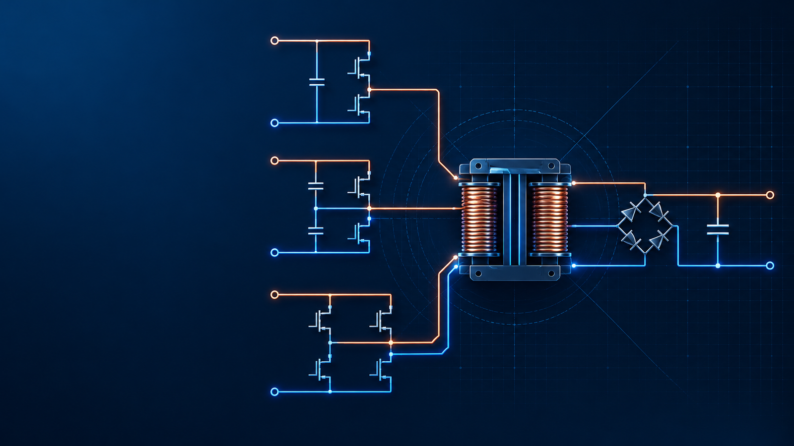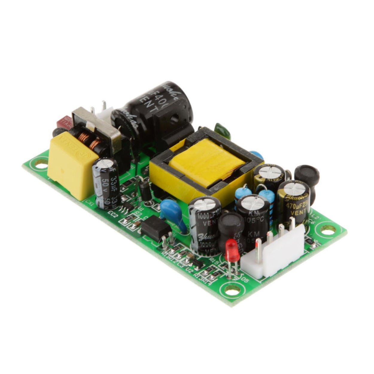
Learn how power factor correction reshapes AC input current, reduces harmonic distortion, supports compliance, and creates a stable high-voltage bus for high-power designs.
Overview
Open a server PSU, a high-output charger, or an industrial AC-DC supply and the input section will often contain a sizeable inductor, a high-voltage switch, a fast diode, and a controller dedicated to power factor correction. Those parts add cost and occupy board area, so their presence raises a fair question: if a switching supply is already efficient, why add another conversion stage?
The short answer is that efficiency and power factor describe different problems. Efficiency tells you how much of the real input power reaches the load. Power factor tells you how effectively the equipment uses the AC distribution system. A supply can be 94% efficient and still draw an ugly, high-crest-factor current waveform that heats cables and transformers and makes harmonic compliance difficult.
PFC fixes that input-current problem. In higher-power equipment, active PFC also creates a controlled high-voltage DC bus, which gives the downstream converter a much easier operating range.
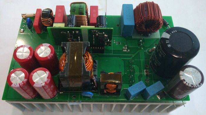
Power factor is not efficiency
For a single-phase AC load, apparent power is calculated from RMS voltage and RMS current:
S = Vrms × Irms
Real power, P, is the power that is converted into output power and losses. Power factor is:
PF = P / S
Efficiency uses a different denominator:
Efficiency = Pout / Pin
This distinction matters in procurement. A high efficiency number does not prove that a supply has low harmonic current, and a high PF number does not prove that the supply wastes little energy internally. Both specifications should be checked at the relevant input voltage and load point.
| Metric | What it describes | Typical question it answers | What it does not prove |
|---|---|---|---|
| Efficiency (%) | Real input power converted to useful DC output | How much heat and energy loss will the supply create? | Whether the AC input current is sinusoidal |
| Power factor | Real power divided by apparent power | How effectively does the load use line current and distribution capacity? | How efficient the internal conversion stages are |
| Input-current THD | Harmonic content of the input current | How distorted is the current waveform? | The complete efficiency or thermal picture |
| Apparent power (VA) | RMS voltage multiplied by RMS current | What current must upstream wiring and switchgear carry? | The useful output power |
Why a bridge rectifier and bulk capacitor draw current in peaks
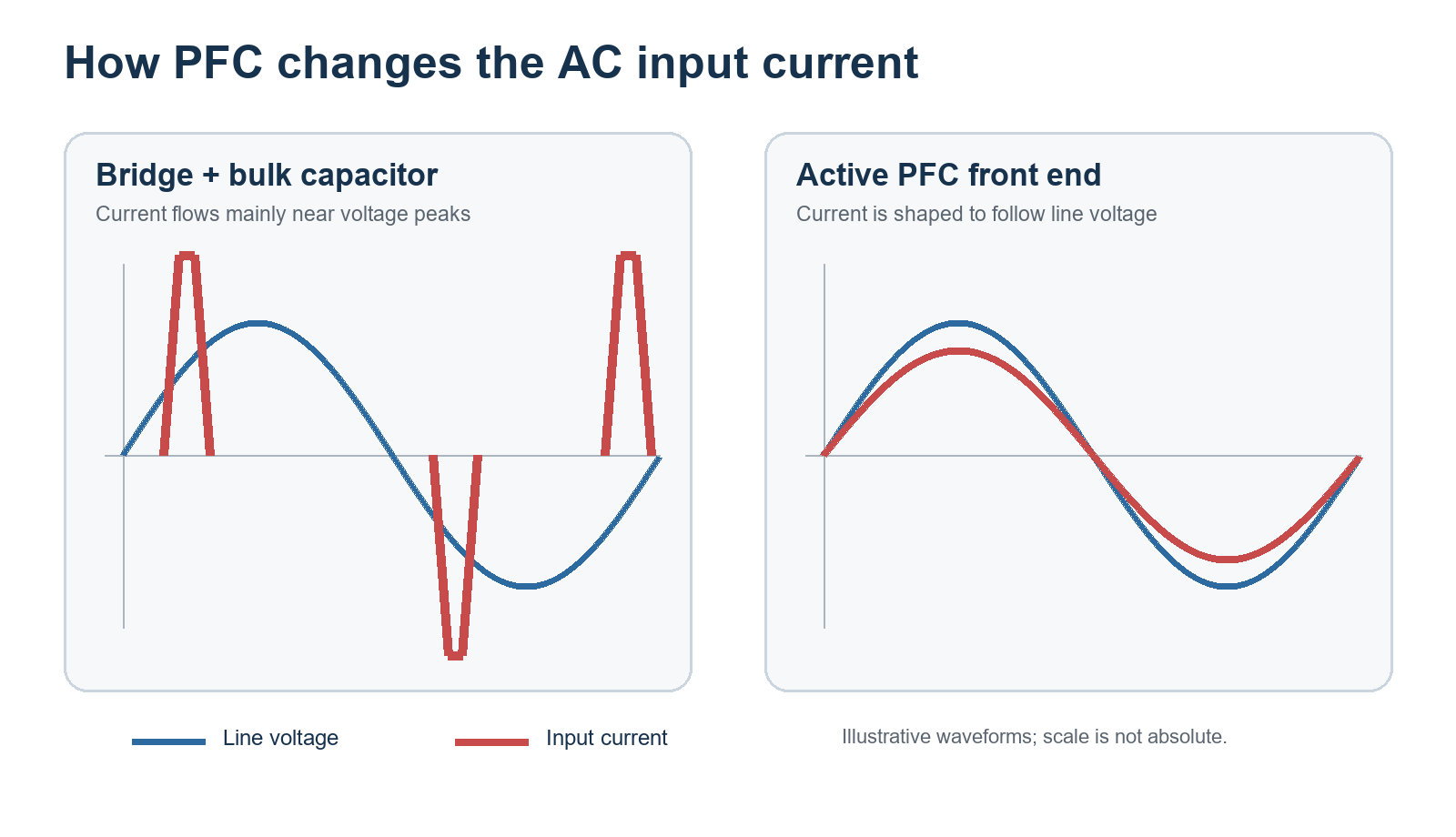
The simplest AC-DC front end uses an EMI filter, a diode bridge, and a large electrolytic capacitor. The capacitor charges near the peak of the rectified line voltage. For much of each half-cycle, the line voltage is below the capacitor voltage, so the bridge does not conduct. When the line rises above the capacitor voltage, it replenishes the stored energy in a short pulse.
The result is a sinusoidal input voltage paired with a narrow, high-amplitude input current. That current contains strong harmonics. The issue is not simply phase displacement, as it would be with an ideal inductive motor load; waveform distortion is often the dominant contributor to low power factor in a capacitor-input supply.
Consider a 400 W DC load supplied at 92% efficiency from 230 VAC. The real AC input power is about 435 W. If PF is 0.60, apparent power is roughly 725 VA and input current is about 3.15 A. At PF 0.98, apparent power falls to about 444 VA and current to about 1.93 A. The load still receives 400 W in both cases. The difference appears upstream, in conductor RMS current, switchgear loading, and transformer capacity.
Those values are illustrative rather than guaranteed design targets. Actual PF depends on line voltage, load, front-end capacitance, conduction angle, and any harmonic-shaping circuit.

What a PFC stage does
Power factor correction reshapes input current so it follows the rectified line voltage. A well-designed active stage can reach PF above 0.95 at rated conditions while keeping individual harmonics within the applicable product limits. It does not eliminate every harmonic, and PF normally degrades at very light load.
Two broad approaches are used.
Passive PFC
Passive PFC uses line-frequency or low-frequency magnetics and capacitors to broaden the charging interval and reduce peak current. It is simple and does not need a control loop, but the magnetic components become bulky as power rises. Performance also varies with line and load. Passive correction can still make sense in cost-sensitive, fixed-input equipment, but it rarely offers the size, harmonic control, or universal-input behavior expected from a modern high-power supply.
Active PFC
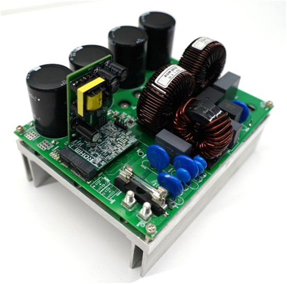
The conventional active front end places a boost converter between the bridge rectifier and the bulk capacitor. A controller regulates the average inductor current against a reference derived from the rectified line. The stage draws current through much more of the line cycle and boosts the bus to a regulated value, commonly around 380 to 400 VDC in universal-input supplies.
The familiar sequence is:
AC input → protection and EMI filter → bridge rectifier → boost PFC → high-voltage DC bus → isolated DC-DC converter
At lower and medium power, critical-conduction-mode designs can offer a useful balance of cost and switching loss. Continuous-conduction-mode and interleaved implementations are common as power rises because they reduce peak current and distribute ripple. Bridgeless and totem-pole PFC stages remove or replace part of the diode-bridge conduction path to improve efficiency, but they demand careful control, sensing, EMI design, and fault management.
Why active PFC becomes attractive as power rises
The commercial case is broader than “better PF.” A high-power front end affects the whole product and the installation around it.
First, harmonic-current limits become harder to meet with a capacitor-input rectifier. IEC 61000-3-2 applies to equipment with rated input current up to and including 16 A per phase when connected to public low-voltage distribution systems. Requirements depend on equipment class, operating conditions, and product category. The often-quoted 75 W threshold is an exemption found in the standard’s framework, but it should not be used as a universal design rule. Lighting equipment and product-specific requirements need separate treatment, and equipment above 16 A per phase can fall under other standards such as IEC 61000-3-12. Certification planning should start from the product classification and target market, not from wattage alone.
Second, a regulated high-voltage bus simplifies the downstream converter. With a plain rectifier, the bulk voltage changes substantially between low-line and high-line operation. Active boost PFC can present a far narrower bus range to an LLC, phase-shifted full bridge, or other isolated stage. That helps transformer optimization, switch selection, gain planning, hold-up design, and control behavior.
Third, lower RMS input current improves the use of branch circuits and cabinet wiring. This is valuable in server racks, telecom rectifiers, charging systems, and industrial control installations where many supplies operate together.

| Design objective | Why PFC helps | What the engineer still has to verify |
|---|---|---|
| Harmonic compliance | Shapes current and reduces low-order harmonics | Correct equipment class, test condition, line voltage, load points, and margin |
| Universal AC input | Maintains a controlled high-voltage bus over a wide line range | Brownout behavior, current stress at low line, and hold-up time |
| Higher rack or cabinet density | Reduces RMS current for the same real input power | Branch-circuit loading, neutral harmonics, diversity, and protection coordination |
| Easier isolated-stage optimization | Narrows the DC-bus range seen by the downstream converter | PFC-bus tolerance, transient response, and DC-DC gain range |
| Higher power density | High-frequency magnetics replace a large passive choke | Switching loss, cooling, EMI, and layout |
What PFC costs the design
Active PFC is an extra conversion stage. It needs an inductor, switching device, boost diode or synchronous path, current sensing, a controller, gate drive, protection, and a bulk capacitor rated for the elevated bus. These parts add loss and failure modes.
Light load is particularly awkward. Gate-charge loss, controller consumption, magnetic loss, and switching transitions remain even when output power is small. Modern controllers respond with burst operation, phase shedding, frequency changes, or PFC disable strategies, but each technique must be checked for audible noise, bus behavior, THD, and downstream compatibility.
Startup also deserves separate design work. The bulk capacitor can draw severe inrush current before normal PFC control begins. NTC thermistors, pre-charge resistors, relays, or controlled semiconductor paths are used to limit that current. A relay that bypasses an NTC after startup can reduce steady-state loss, but its timing and fault response matter.
The voltage loop and current loop introduce another risk. Poor compensation, noisy sensing, or a bad high-current layout can distort input current, make the bus oscillate, or overstress the MOSFET and diode. A PF value measured at full load does not replace dynamic tests at low line, light load, load steps, brownout, startup, and abnormal conditions.
Choosing between no PFC, passive PFC, and active PFC
| Option | Best fit | Main advantages | Main limitations |
|---|---|---|---|
| No dedicated PFC | Low-power products that meet applicable harmonic limits without correction | Lowest cost and part count | Pulsed input current, variable bulk bus, limited scalability |
| Passive PFC | Cost-sensitive equipment with constrained performance targets | Simple, rugged, no active control loop | Heavy magnetics, modest correction, line/load sensitivity |
| Active boost PFC | Most medium- and high-power universal-input AC-DC supplies | High PF, low THD, regulated bus, strong compliance margin | Added cost, loss, control complexity, inrush and EMI work |
| Interleaved or bridgeless active PFC | Higher-power or high-density platforms | Lower ripple or conduction loss, better thermal spreading | More switches, sensing, control, and layout complexity |
For a B2B buyer, the topology label is only the start. Ask for PF and THD curves at the intended line and load, not a single best-case number. Confirm the harmonic standard and equipment class used for testing. Check inrush current, bus hold-up time, light-load behavior, protection recovery, conducted emissions, component temperature rise, and bulk-capacitor lifetime assumptions.
Common misconceptions
“PFC improves the efficiency rating.” Not inherently. It can reduce upstream distribution losses, but the PFC stage itself dissipates power. System efficiency must be measured.
“PF of 0.99 means there are no harmonics.” No. It means real and apparent power are close at that operating point. Residual harmonics still exist, so harmonic-current data and THD remain relevant.
“Every supply above 75 W is legally required to contain active PFC.” Standards regulate emissions, not a specific circuit. Some products can comply through another method, and the applicable threshold depends on classification and market. Active PFC is common because it is an effective engineering solution.
“A 400 V PFC bus is universal.” It is common, not mandatory. Designers choose the setpoint and operating window around line range, semiconductors, hold-up energy, downstream topology, and transient margin.
Final engineering takeaway
PFC earns its place in a high-power AC-DC supply by controlling how the product interacts with the mains. It reduces distorted line current, improves the use of upstream capacity, supports harmonic compliance, and gives the isolated converter a stable high-voltage input. None of that should be confused with conversion efficiency.
The right purchasing specification therefore includes both sides of the problem: efficiency and thermal performance inside the supply, plus PF, THD, inrush, and harmonic compliance at the AC input. SIPURUI can support industrial power-supply selection around input range, load profile, installation density, and target-market compliance rather than treating “active PFC” as a box-ticking feature.