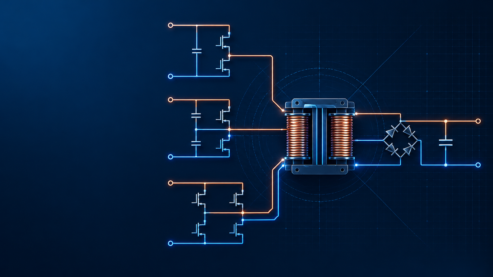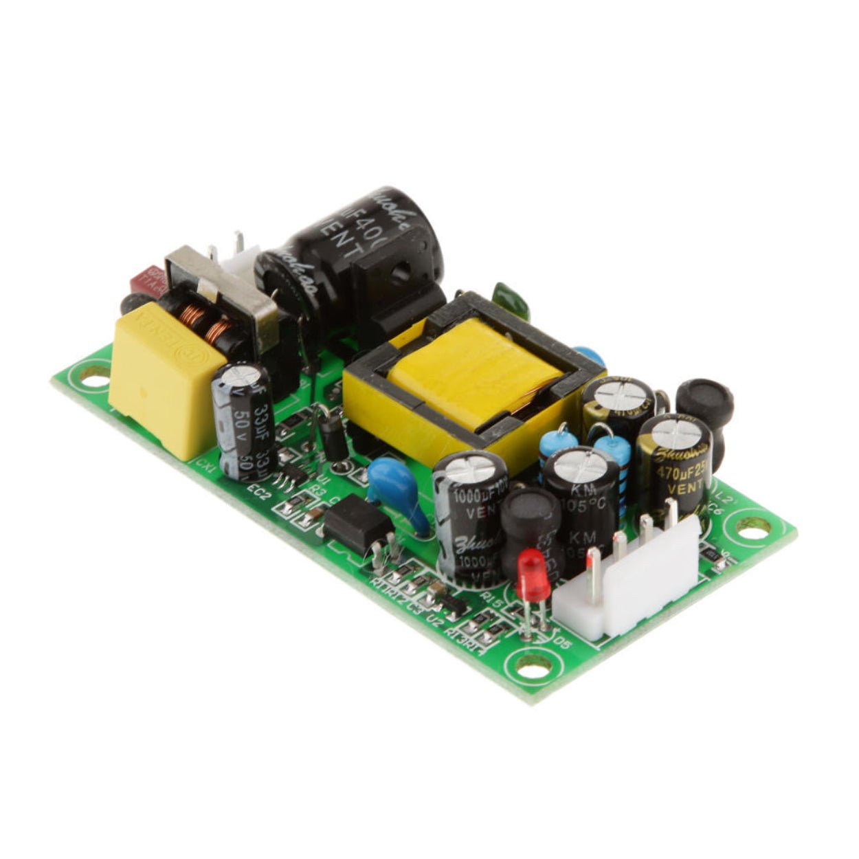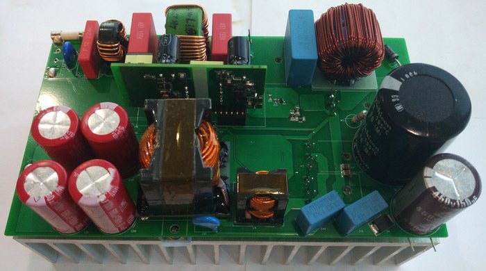
Choosing between an isolated and a non-isolated power supply is a system decision shaped by voltage exposure, accessible outputs, grounding, EMC, efficiency, and fault behavior.
Overview
Choosing between an isolated and a non-isolated power supply is a system decision, not a preference for one converter topology over another. The right answer depends on what voltage can appear at the input, whether anyone can touch the output, how grounds are connected, and what must happen when a component fails.
That distinction matters in procurement as much as in circuit design. A low-cost DC-DC module marked "isolated" may provide only functional insulation. It can separate grounds for signal integrity, yet still be unsuitable as a shock-protection barrier. At the other extreme, adding reinforced isolation after an already isolated adapter may increase cost, size, losses, and EMI work without improving the product.
This guide explains the trade-offs and gives engineers, equipment manufacturers, and industrial buyers a practical route to a defensible choice.
What electrical isolation actually means
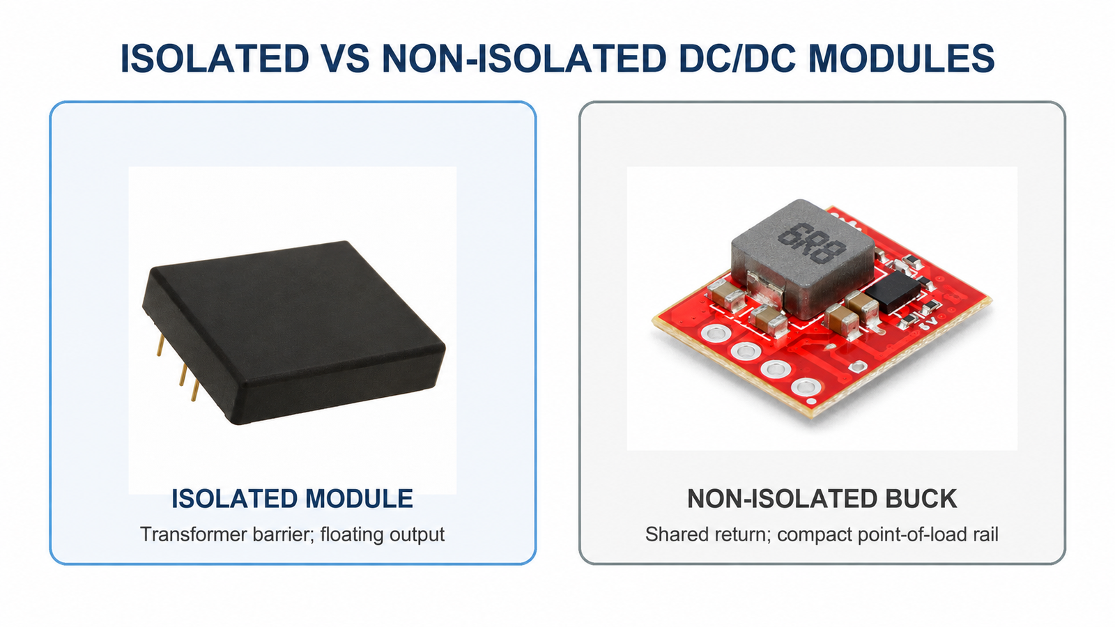
A non-isolated converter has a conductive relationship between input and output. In a typical buck converter, the input return and output return are the same node. Energy moves through switches, an inductor, and capacitors without a transformer or another rated isolation barrier. Buck, boost, buck-boost, SEPIC, and linear regulators are common non-isolated choices.
An isolated converter transfers energy across an insulation barrier, most often through a transformer. Its primary and secondary circuits do not need a direct conductive connection. Flyback, forward, push-pull, half-bridge, and full-bridge converters can all be built as isolated topologies.
The transformer is only part of the barrier. The PCB, optocoupler or digital feedback path, Y capacitors, connectors, enclosure, and manufacturing process must preserve the required insulation. Creepage and clearance depend on working voltage, transient category, pollution degree, material group, altitude, and the applicable product standard. A headline withstand voltage alone does not prove that an assembly is safe for a given use.
Insulation is normally classified as functional, basic, supplementary, double, or reinforced according to the role it performs in the finished equipment. Functional insulation allows a circuit to operate correctly but is not, by itself, protection against electric shock. Reinforced insulation can provide protection equivalent to double insulation, yet its required spacing, materials, and test conditions still depend on the applicable equipment standard and the actual working environment.
Isolation purpose comes before topology
Before comparing flyback with buck or selecting a module, write down why the barrier is needed. Most projects fall into one or more of these categories:
Safety isolation keeps hazardous voltage from reaching accessible circuits under normal and specified fault conditions.
Functional isolation allows two circuit sections to operate at different reference potentials or breaks a ground loop. It may not provide shock protection.
Noise and transient containment limits the transfer of disturbances between domains, although no practical barrier is perfect at high frequency.
These purposes lead to different component ratings and verification plans. An isolated transceiver node powered from a 24 V industrial bus may need functional insulation and strong common-mode transient immunity. A mains-powered accessible USB or sensor output requires a safety barrier designed and certified for the applicable equipment standard.
Side-by-side engineering comparison
| Design factor | Non-isolated supply | Isolated supply |
|---|---|---|
| Input-output relationship | Conductive path; grounds are usually shared | Energy crosses an insulation barrier; grounds may remain separate |
| Typical topologies | Buck, boost, buck-boost, SEPIC, LDO | Flyback, forward, push-pull, half-bridge, full-bridge |
| Shock protection | No protection from input voltage by itself | Can provide basic or reinforced protection when the full barrier is correctly designed and certified |
| Ground-loop control | Cannot break the power-ground path | Can interrupt ground-loop current between domains |
| Common-mode behavior | Shared ground simplifies some local return paths, but input disturbances can propagate directly | Barrier capacitance carries high-frequency common-mode current; EMI control remains necessary |
| Efficiency and density | Often favorable at low and medium power because there is no isolation transformer | Transformer, rectification, clamps, and barrier components add losses and space |
| Design and qualification | Usually fewer components and simpler magnetics | Requires transformer design, insulation coordination, barrier-aware layout, and dielectric testing |
| Fault consequence | A failed switch can connect the input rail to the output | The barrier can prevent primary faults from reaching the secondary, provided its insulation remains intact |
| Cost | Usually lower | Usually higher, especially when certified reinforced insulation is required |
Safety is more than a transformer symbol
For a hazardous input, start with the product's required means of protection. Ask who can touch the output, whether a service technician can access it, and what happens after a single fault. Then identify the governing standard. Industrial control equipment, information technology equipment, household appliances, and medical devices do not share identical insulation and leakage-current rules.
Do not treat "3 kV isolation" on a module listing as a complete safety specification. Confirm at least the following:
| Item to verify | Why it matters |
|---|---|
| Insulation classification | Functional, basic, supplementary, double, and reinforced insulation serve different safety roles |
| Working voltage | A short dielectric test does not establish continuous working-voltage capability |
| Creepage and clearance | Required distances change with environment, material, altitude, and overvoltage conditions |
| Test method and duration | AC, DC, and impulse tests are not interchangeable headline numbers |
| Certification and end-product conditions | A recognized component may still impose PCB spacing, fusing, enclosure, or thermal conditions |
| Barrier capacitance and leakage | These affect common-mode current, touch current, and EMC behavior |
A design that keeps hazardous voltage inside a locked industrial enclosure may use non-isolated auxiliary conversion in areas inaccessible to operators. That choice must be supported by the complete enclosure, protective earth, interlocks, fusing, servicing rules, and end-product standard. It should not be copied into an accessible product simply because it worked in another machine.
Isolation changes EMI; it does not remove it
An isolation transformer blocks DC conduction, but its primary-to-secondary capacitance still couples high-frequency current. Fast switch-node voltage transitions create common-mode displacement current through that capacitance. Feedback components, heatsinks, shielding, and PCB overlap can add more paths.
Designers often add a safety-rated Y capacitor to give this current a controlled return path. The trade-off is leakage or touch current. Increasing Y capacitance may reduce common-mode emissions while making the leakage-current limit harder to meet. The capacitor therefore has to be selected as part of the complete safety and EMC design, with its safety class, capacitance, working voltage, and failure behavior checked against the end-product requirements.
Non-isolated converters avoid transformer interwinding capacitance, but they are not automatically quiet. Their high di/dt loops and switch nodes can produce substantial conducted and radiated emissions. Layout remains decisive: short switching loops, controlled return paths, sensible component placement, and an appropriate input filter usually matter more than the topology label alone.
Efficiency, size, and cost need an operating point
Non-isolated conversion often wins on efficiency, density, and BOM cost when input and output voltages are in the same low-voltage system. There is no isolation transformer to design, qualify, and accommodate. Synchronous bucks are particularly effective for point-of-load rails.
Isolation introduces winding resistance, core loss, leakage-inductance spikes, rectifier or synchronous-rectifier loss, and often a clamp or snubber. At light load, housekeeping and magnetizing losses may matter more than full-load efficiency. At high power, however, an isolated resonant or phase-shifted topology can be highly efficient. Fixed statements such as "isolated supplies are always 85% to 92% efficient" are too broad for purchasing decisions.
Compare candidate supplies at the expected input voltage, load profile, ambient temperature, and cooling condition. Also check standby consumption, derating, transient capability, and lifetime-critical component temperatures. A one-point peak-efficiency figure rarely predicts energy use or reliability in the finished machine.
How to choose for common applications
| Application | Usual direction | Selection logic |
|---|---|---|
| Battery-powered internal rails | Non-isolated | The source is normally extra-low voltage; efficiency and compact size dominate |
| Board rails after an approved AC-DC adapter | Non-isolated | The upstream supply already provides the safety barrier; add isolation only for another defined need |
| Accessible output from mains | Isolated | The barrier must provide the required means of protection under the relevant standard |
| PLC, RS-485, CAN, or 4-20 mA nodes with ground-potential differences | Often isolated | Power and signal isolation can break circulating ground current and improve fault tolerance |
| High-side sensing in an inverter or motor drive | Isolated | The control domain must tolerate large common-mode voltage and transients |
| Floating sensor bias or gate drive | Isolated | The output reference must move independently of the controller ground |
| Sealed high-voltage subassembly | System-dependent | Non-isolated conversion may be possible only when the enclosure and end-product protection control access and faults |
For battery equipment, select buck when the input always exceeds the output, boost when it remains below, and buck-boost when it crosses the desired output. A four-switch buck-boost is often the cleanest answer when a battery moves through both regions.
For isolated low-to-medium-power AC-DC supplies, flyback remains common because it uses relatively few power-stage components and supports multiple outputs. Forward-derived converters become attractive as power, ripple, and current requirements rise. Bridge and resonant topologies cover higher-power designs, but power level alone does not set the boundary; thermal limits, input range, hold-up time, regulation, and cost also matter.
A practical selection sequence
1. Define the input source, maximum continuous voltage, and expected surge or transient environment.
2. Mark every accessible conductive part and every interface leaving the enclosure.
3. Identify the applicable product safety standard and the required means of protection.
4. Decide whether grounds may be connected. Include cable shields, protective earth, test equipment, and communication ports in the drawing.
5. Check whether the system needs a floating rail, ground-loop interruption, or high common-mode transient immunity.
6. Compare loss, thermal rise, volume, cost, availability, and qualification effort at the real operating points.
7. Verify the complete isolation barrier, including transformer, feedback path, PCB spacing, connectors, and manufacturing controls.
8. Test dielectric strength, leakage or touch current, surge, EFT, ESD, emissions, immunity, and fault behavior as required by the product.
Common selection mistakes
Assuming isolated means touch-safe. A functionally isolated module may be appropriate for breaking a ground loop and still fail the requirements for an accessible mains-derived output.
Expecting isolation to cure every EMC problem. Barrier capacitance can create a common-mode path. Conversely, a shared ground in a non-isolated design can carry disturbances directly into sensitive circuits.
Repeating isolation without a stated purpose. After an approved adapter has created a safe low-voltage bus, local bucks usually provide the best point-of-load solution. A second barrier is justified when the system needs another safety boundary, a floating domain, or ground-loop control.
Comparing catalog efficiency without the load profile. Transformer loss does not make every isolated design inefficient, and a high peak figure does not guarantee low heat at the actual operating point.
Ignoring what happens during a fault. In a non-isolated buck, a shorted high-side switch can expose the output to the input rail. Protection must be designed around the damage that rail can cause. In an isolated converter, barrier failure is a critical event, while secondary rectifier, feedback, and regulation failures still require suitable overvoltage and overcurrent protection.
A balanced system architecture
Many products use one certified isolated front end followed by non-isolated point-of-load converters. The first stage establishes the safety boundary and produces a safe DC bus. Local bucks or buck-boost converters then generate processor, sensor, relay, and communication rails efficiently.
Extra isolated DC-DC modules are added only where a domain genuinely needs to float, withstand a ground difference, or meet another protection requirement. This architecture makes the safety boundary easy to review and avoids paying the isolation penalty on every rail.
Final recommendation
Choose isolation when the design must protect people from hazardous voltage, keep a circuit at an independent potential, or interrupt an unwanted ground-current path. Choose non-isolated conversion when the source is already safe, grounds may be shared, and efficiency, size, and cost matter more than a new barrier.
The purchasing specification should state the insulation class, working voltage, test voltage and duration, creepage and clearance conditions, leakage or touch-current limit, barrier capacitance, approvals, and fault expectations. "Isolated" is not enough.
SIPURUI can help equipment manufacturers compare isolated and non-isolated power architectures against input range, load profile, mechanical constraints, EMC targets, and certification needs before a supply is committed to production.