A practical 21-point power supply design checklist covering line regulation, load changes, ripple, inrush current, protection, thermal drift, safety, EMC and environmental testing.
Overview
When an electronic product behaves strangely, the power rail is often the first place an experienced engineer looks. A PLC resets when a relay pulls in. A sensor reads cleanly on the bench but drifts in a cabinet. A communication module passes functional testing, then fails after a surge event at the customer site. The root cause is not always the power supply, but weak power design gives many other problems a place to start.
The useful question is not whether a power supply can produce the rated voltage under ideal conditions. It is whether it can stay within limits while the AC line moves, the load changes, the temperature rises, and nearby equipment adds electrical noise.
This checklist reorganizes 21 common power supply design points into a practical review path for hardware engineers, automation integrators, OEM equipment builders, and technical buyers. It applies to many AC-DC and DC-DC supplies, including industrial 24 VDC systems, embedded electronics, communication equipment, LED devices, and control cabinets.
1. Line Regulation: Will the Output Stay Stable When the Input Moves?
Input voltage is rarely as clean as a datasheet test condition. Industrial sites may see brownouts, long wiring runs, generator power, high line during light load periods, or regional mains differences. For a DC-DC converter, the upstream bus may sag during motor start or battery discharge.
Line regulation describes how much the output voltage changes when the input changes while the load remains constant. A lower value means the output is less sensitive to mains or bus movement. Datasheets may express this as an absolute voltage change, a percentage, or a regulation coefficient.
For a buyer, the practical check is simple: compare the input range and line regulation with the worst input conditions expected in the field. A universal-input AC-DC supply may accept a wide nominal range, but the engineer still needs to check hold-up time, derating, thermal behavior, and compliance at the operating extremes.
2. Load Regulation: What Happens When the Equipment Starts Working?
Many products do not draw steady current. Solenoids, motors, radios, heating elements, displays, relays, and processors can all create fast or stepped load changes. Load regulation measures output voltage change as load current moves, commonly from no load to rated load or across a specified load range.
Low output resistance is part of the same story. The smaller the effective output resistance, the less the output rail drops when current increases. In a control cabinet, this can be the difference between a stable 24 V rail and nuisance faults when multiple devices switch at once.
Do not size the supply only from steady-state current. List the normal current, peak current, startup current, duty cycle, cable voltage drop, and margin. This is especially important when one supply feeds mixed loads such as PLC modules, sensors, valves, and communication devices.
| Check area | What to review | Practical risk if ignored |
|---|---|---|
| Input range | Minimum and maximum AC or DC input under real installation conditions | Brownout resets, overheating at low line, approval mismatch |
| Line regulation | Output change across input variation | Analog drift, unstable logic rails, process errors |
| Load regulation | Output change from light load to rated load | Voltage drop during machine cycles |
| Output resistance | Rail stiffness as current changes | Cable and load transients become visible at the device |
| Hold-up time | Output support during short input interruptions | Controller reboot during brief mains dips |
3. Ripple and Noise: Do Not Treat the mV Number Casually
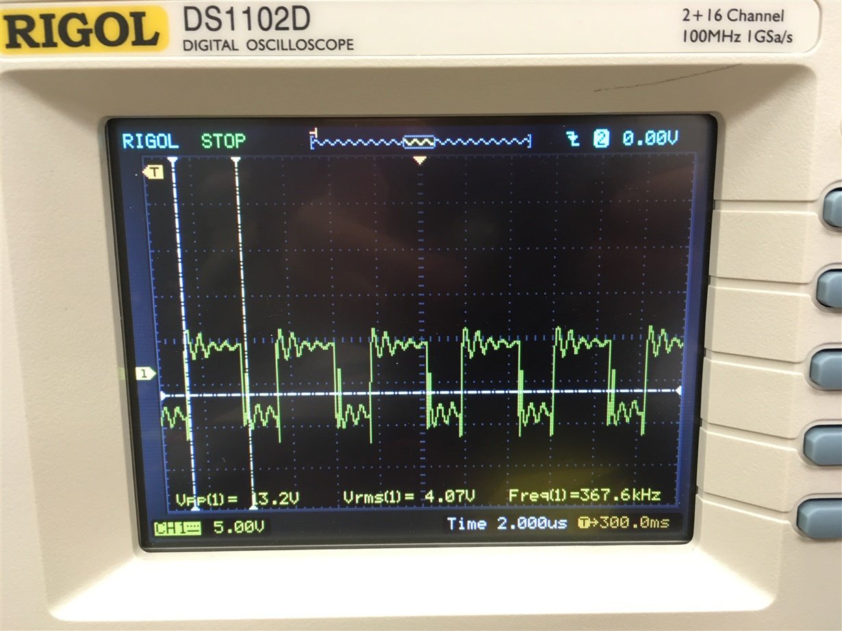
Ripple is the repeating AC component left on the DC output. In a switching supply, it often relates to the switching frequency and output filter behavior. Noise is the higher-frequency content caused by switching edges, layout parasitics, diode recovery, transformer coupling, and measurement pickup. They are often specified together as ripple and noise, usually in mV peak-to-peak.
The number is only meaningful when the test condition is clear. Bandwidth limit, probe method, external capacitors, load current, ambient temperature, and grounding all change the reading. Bel Fuse notes that ripple and transient measurements depend heavily on correct oscilloscope probing, and a 20 MHz bandwidth limit is commonly used for this type of measurement.
For sensitive analog circuits, encoders, sensors, medical instruments, and communication equipment, confirm the ripple limit under rated load and the exact test setup. A low-cost supply can look acceptable with a long probe ground lead and then fail once the measurement is done properly.
4. Inrush Current: The First Half-Cycle Can Be Hard on the System
When an AC-DC power supply is switched on, input capacitors charge quickly. The resulting inrush current can be much higher than the normal operating current. Typical supplies may show tens of amps for a short time, depending on input voltage, capacitance, NTC thermistor temperature, topology, and timing.
Inrush matters when several power supplies start together, when an upstream breaker is small, or when equipment is restarted quickly while the inrush limiter is still hot. Check the datasheet value, startup temperature condition, and recommended breaker or fuse rating. In panel systems, staggered startup or soft-start behavior may prevent nuisance trips.
5-8. Protection Functions: Define the Fault Behavior Before the Fault Happens
Protection is not only a checkbox. A power supply can shut down, limit current, enter hiccup mode, latch off, recover automatically, or keep operating in a reduced state. Each behavior has a different effect on the connected equipment.
Overcurrent protection prevents overload or short-circuit current from damaging the supply, wiring, or load. A common trip or limit range is around 110% to 130% of rated current, but actual behavior varies by model. For motors, capacitive loads, and solenoids, make sure startup current does not accidentally trigger a fault.
Overvoltage protection protects downstream circuits from an excessive output voltage. Some designs clamp the rail, some shut down, and some require power cycling. A typical protection threshold may sit around 130% to 150% of rated output, but it must be verified against the load's absolute maximum rating.
Undervoltage protection matters when a low rail could cause unsafe logic states or false machine operation. Some systems should shut down cleanly or alarm if the output drops below a defined threshold. In automation, this is often tied to DC OK contacts, PLC diagnostics, or system-level fault handling.
Overtemperature protection prevents internal parts from continuing to run beyond safe limits. It is a last defense, not a substitute for thermal design. If the supply frequently reaches thermal shutdown, the enclosure, derating, airflow, mounting spacing, or load margin needs to be revisited.
| Protection function | Typical purpose | Design review question |
|---|---|---|
| Overcurrent / overload | Protects the supply and wiring during excess load or short circuit | Does it current-limit, hiccup, latch off, or recover automatically? |
| Overvoltage | Protects downstream electronics from an excessive rail | Is the threshold below the load's damage limit? |
| Undervoltage | Prevents bad logic states or unsafe operation at low voltage | Does the system alarm or shut down cleanly? |
| Overtemperature | Prevents heat-related damage inside the supply | Is normal operation far below shutdown temperature? |
| Short-circuit protection | Handles wiring errors and field faults | How long can the supply tolerate the short? |
9. Temperature Drift: Check Output Accuracy Across the Real Ambient Range
Resistors, references, optocouplers, capacitors, magnetic parts, and control ICs all change with temperature. Temperature drift describes output voltage change as ambient temperature changes, often expressed as V/C, mV/C, or a percentage per degree.
For ordinary industrial rails, small drift may not matter. For precision instrumentation, sensor excitation, medical devices, and analog measurement systems, it can be critical. Review the full operating temperature range, not only room-temperature accuracy.
10. Long-Term Drift: Components Age Even When Conditions Look Stable
Even with constant input voltage, load, and temperature, the output may shift over time. Reference aging, capacitor aging, optocoupler current transfer ratio change, solder joint stress, and thermal cycling can all contribute. High-precision regulators usually specify drift over a defined time window.
For long-life equipment, the question is not only "does it pass final test today?" It is whether the rail stays inside tolerance after months or years of heat, load, and cycling. This is one reason conservative capacitor selection and derating matter.
11. Transient Response: Step Loads Reveal Weak Control Loops
Transient response is the output voltage behavior when load current changes suddenly. A relay bank energizes, a radio transmitter turns on, or a processor enters a high-current state. The supply cannot react instantly, so output capacitors and loop compensation carry the first part of the event.
Review voltage deviation, recovery time, and test conditions. If the product has fast load steps, ask for scope captures or run a test with a dynamic load. A supply with acceptable steady-state regulation can still produce a deep dip or overshoot during a step event.
12. Output Waveform Distortion: Relevant for AC Output Supplies and UPS Systems
For DC supplies, ripple and transient behavior usually matter more than sine-wave distortion. For AC regulators, inverters, and UPS outputs, waveform distortion becomes a direct quality metric. Motors, transformers, audio equipment, and measurement devices may behave poorly with distorted AC output.
Check total harmonic distortion, load type, crest factor, and how the output behaves with nonlinear loads. A clean no-load waveform does not guarantee clean operation under real equipment load.
13-16. Noise, Surge, ESD, and EMC: Design for the Electrical Environment
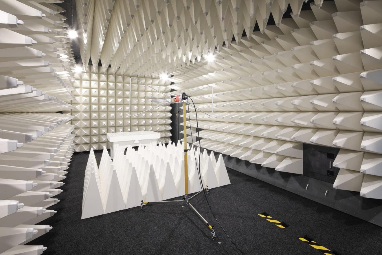
Power supplies both receive and create interference. Conducted noise travels along cables below roughly 30 MHz. Radiated noise couples through space and becomes harder to manage as frequency rises. Fast switching edges are useful for efficiency but unforgiving to layout, shielding, grounding, and filtering.
Input noise immunity is the ability to keep operating when the mains or DC input carries pulses, dips, bursts, or disturbances. Surge immunity covers high-energy events caused by lightning coupling, large inductive switching, and distribution disturbances. ESD immunity covers static discharge to accessible surfaces, terminals, and enclosure points.
EMC is not a decoration added at the end. It starts with PCB layout, creepage and clearance, filter placement, Y-capacitor return paths, shielding, bonding, cable routing, enclosure design, and correct test planning. Standards such as the IEC 61000-4 series are commonly used for immunity test methods, while emission requirements depend on product category and market.
17. Overall Stability: Combine Input, Load, Temperature, and Time
Overall stability is the combined output variation under allowed input, load, temperature, and time conditions. This number is more useful than a single regulation figure because field conditions do not move one variable at a time.
For power supply selection, ask which specifications are independent and which are combined. Some datasheets list line regulation, load regulation, ripple, temperature coefficient, and set-point accuracy separately. Others provide a total regulation band. For critical loads, build a tolerance budget so downstream circuits still work at the worst credible rail voltage.
18. Electrical Safety: Use Current Standards, Not Old Reference Numbers
The original Chinese notes behind this topic mention older safety references such as GB 4943-90. For current publishing and product selection, it is better to avoid presenting obsolete numbers as the active requirement. China now uses GB 4943.1-2022 for audio/video, information technology, and communication technology equipment safety, and the national standard information platform lists it as current with implementation from August 1, 2023. The IEC page for IEC 62368-1:2018 describes the modern hazard-based safety approach for AV/ICT equipment up to 600 V.
In practical power supply design, safety review usually includes creepage and clearance, dielectric withstand testing, insulation system design, leakage current, protective earth continuity where applicable, fire enclosure behavior, PCB flammability rating, transformer insulation, and component approvals. The exact requirement depends on product category, installation environment, altitude, pollution degree, working voltage, and target market.
Do not copy spacing or leakage values from an old checklist without confirming the applicable standard. A number that was acceptable for one class of equipment, one voltage, or one national rule may be wrong for another product.
19. Radio Disturbance and Emissions: The Supply Must Be Quiet Enough for Its Market
The older GB 9254-1998 reference has also been superseded in modern contexts. China's GB/T 9254.1-2021 covers EMC emission requirements for information technology equipment, multimedia equipment, and receivers, and is listed as current by the national standards platform.
For an exported product, the applicable route may involve CISPR, EN, FCC, GB/T, or other market-specific requirements. The power supply is often a major contributor to conducted emissions at the mains terminal and radiated emissions through cables and enclosure openings. Passing emissions usually requires both a competent supply and a system layout that does not undo the supply's filtering.
20. EMC Immunity: The Product Must Survive the Customer's Site
Emission limits protect other equipment. Immunity tests protect your product from the real world. Common tests include ESD, electrical fast transients, surge, conducted RF immunity, radiated RF immunity, power-frequency magnetic field, voltage dips, short interruptions, and conducted/radiated disturbance checks.
The test levels depend on product standard and environment. A laboratory instrument, home appliance, telecom product, factory control panel, and outdoor equipment do not share the same risk profile. For B2B equipment, define the installation class early. It is much cheaper to design the filter, grounding, and enclosure correctly than to repair EMC failures after tooling and certification scheduling are already committed.
21. Environmental Testing: Verify the Supply Outside the Comfortable Bench
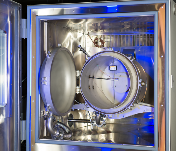
Power supplies experience storage, shipping, vibration, hot cabinets, cold starts, humidity, salt air, dust, altitude, and repeated power cycling. Environmental tests expose weak solder joints, marginal capacitors, poor terminal design, insulation weakness, fan reliability problems, and enclosure sealing issues.
Relevant tests may include low temperature, high temperature, damp heat, temperature cycling, vibration, shock, salt spray, dust, low pressure, solderability, terminal strength, flammability, sealing, and packaging transport tests. The goal is not to collect test names. The goal is to choose tests that match how the product will be shipped, installed, cleaned, powered, and serviced.
A Practical Review Table for Design and Purchasing
The best checklist is the one that catches problems before prototypes become field failures. Use the table below as a review tool during schematic design, supplier selection, incoming inspection, or product approval.
| Design area | Minimum review item | Evidence to request or generate |
|---|---|---|
| Input behavior | Input range, line regulation, hold-up time, inrush | Datasheet limits, startup waveform, breaker/fuse check |
| Output quality | Load regulation, ripple/noise, transient response | Dynamic load test, oscilloscope capture, measurement setup notes |
| Protection | OCP, OVP, UVP, OTP, short-circuit mode | Fault test report and recovery behavior description |
| Thermal margin | Derating curve, hot-spot temperatures, airflow assumptions | Thermal image or thermocouple data at worst ambient |
| Safety | Insulation, creepage/clearance, dielectric test, leakage current | Current certificates, construction review, transformer approval |
| EMC | Conducted/radiated emissions and immunity | Pre-scan data, certified lab report, cable/grounding notes |
| Reliability | Capacitor life, component derating, environmental tests | BOM review, lifetime estimate, temperature/humidity/vibration reports |
Common Mistakes That Still Pass a Quick Bench Test
A supply can output 24 V on the bench and still be wrong for the product. Common mistakes include using no-load accuracy as proof of regulation, measuring ripple with a noisy probe loop, ignoring inrush when several supplies start together, choosing a supply without enough thermal derating, placing EMI filters far from the connector, routing noisy switch nodes under feedback traces, treating protection thresholds as exact values, and relying on obsolete standard references.
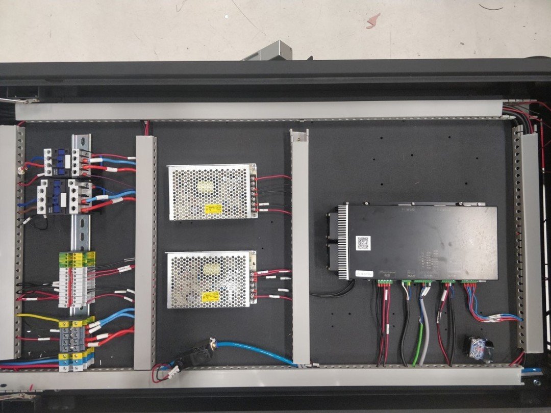
Another common mistake is buying only from the current rating. A 24 V 5 A supply for a sealed LED box is not the same engineering choice as a 24 V 5 A supply for a PLC cabinet with inductive loads. The load, environment, certification path, wiring, and expected service life should drive the selection.
Conclusion
Good power supply design is not mysterious, but it is easy to underestimate. Stable voltage, low ripple, controlled startup current, clear protection behavior, thermal margin, current safety standards, EMC readiness, and environmental validation all work together. Miss one area and the product may still work during a short test, then fail when the customer installs it in a hotter, noisier, more demanding place.
For OEM equipment builders and industrial buyers, the safest approach is to turn these 21 points into an engineering and procurement checklist. SIPURUI supports switching power supply projects where reliable output, practical protection, and application fit matter as much as the nameplate rating. If you are selecting a supply for automation, LED equipment, communication hardware, or custom electronics, review the real load and environment first; the model number should come after that.
Buyer Checklist
- Compare input range, line regulation and hold-up time with the worst field conditions.
- Size the supply from normal current, peak current, startup current, cable drop and temperature margin.
- Confirm ripple/noise measurement conditions before accepting a datasheet number.
- Review OCP, OVP, UVP, OTP and short-circuit behavior against the actual load.
- Check safety, EMC and environmental evidence against current standards and target markets.