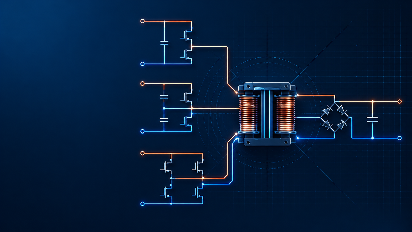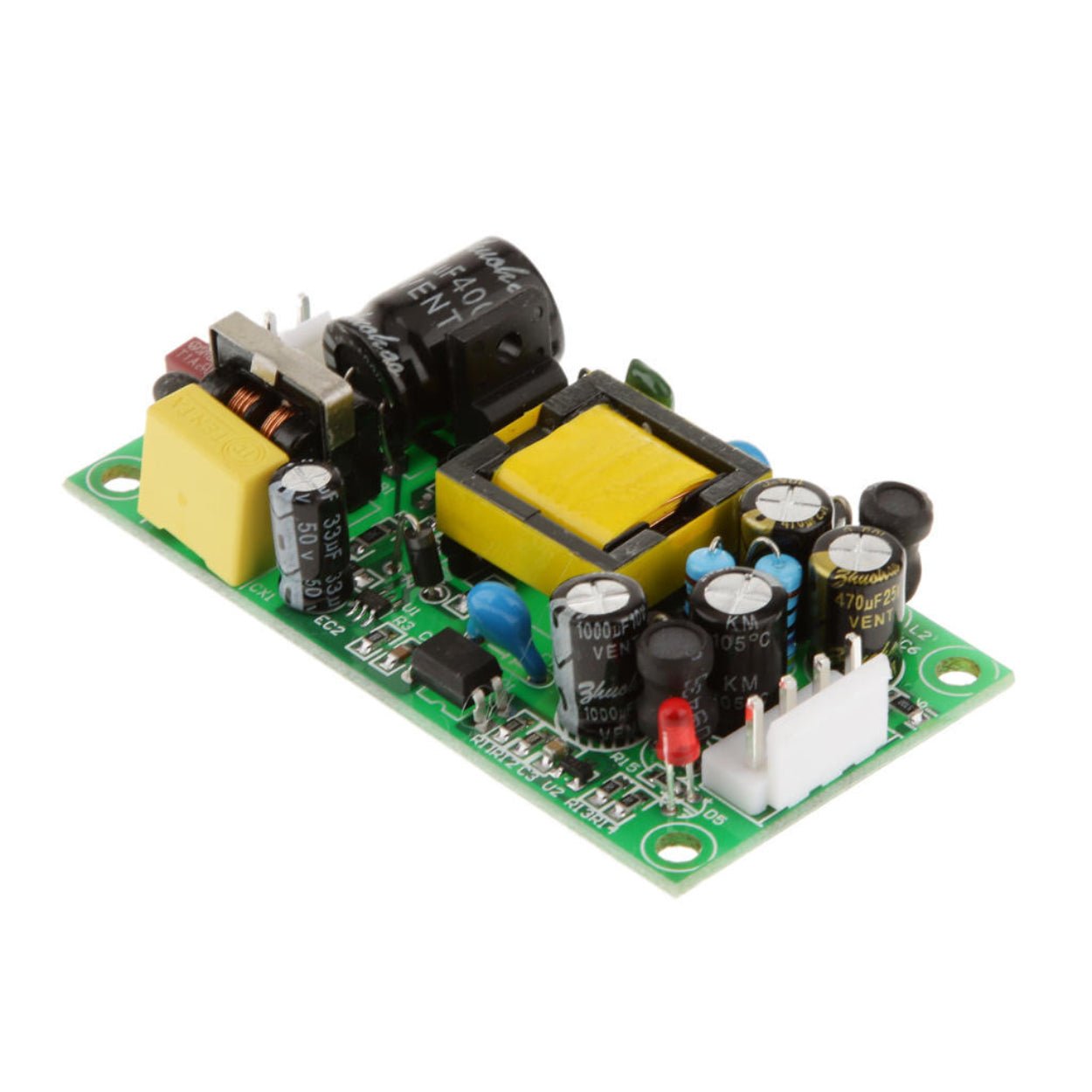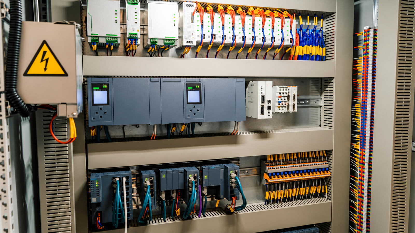
Topology selection should start with input range, output voltage, current, power level, isolation, thermal limits, cost, size, and EMC risk. This guide explains how to shortlist non-isolated and isolated SMPS topologies for real industrial applications.
Overview
Choosing a power supply topology too early can make the rest of the design harder than it needs to be. A flyback may look attractive because the part count is low, then struggle with transformer stress and EMI at the required power. A compact buck regulator may seem simple until the input range crosses the output voltage. A full-bridge converter may deliver good efficiency, but its cost and control complexity can be out of place for a modest auxiliary supply.
For engineers and purchasing teams, topology selection should start before schematic work and supplier quotations. It is the point where electrical requirements, product constraints, compliance needs, and business tradeoffs meet. The right choice will not guarantee a quiet, cool, reliable supply by itself. The wrong choice, however, can force the team into expensive fixes later.
This guide turns the usual topology question into a practical selection process for industrial, automation, LED, communication, test equipment, and OEM power supply projects.
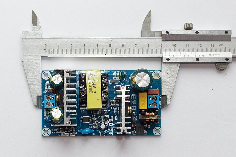
Start with the requirements, not the circuit
The first question is not "Which converter is best?" It is "What must this power supply actually do?"
At minimum, define the input voltage range, output voltage, output current, maximum power, isolation requirement, load behavior, and operating environment. A 24 V industrial output powered from a stable 48 VDC bus has a very different topology path from a universal-input AC-DC supply feeding motor controls inside a warm cabinet.
Do not treat nominal voltage as enough. Many real installations have brownout, surge, long cable drops, battery discharge, or wide utility variation. If a DC input can fall below and rise above the target output, a simple buck or boost converter may no longer fit. If the user can touch the output, if the product crosses an AC mains boundary, or if different ground systems are involved, isolation becomes a design and compliance requirement rather than a preference.
Thermal limits should be written down at the same stage. A topology that reaches 92% efficiency on an open bench may still fail in a sealed enclosure at 55 degrees C ambient. The same applies to space. A larger transformer, more MOSFETs, extra demagnetizing parts, or a heatsink can be acceptable in a rack-mounted product and impossible in a compact controller.
| Design input | Why it affects topology | Practical question to answer early |
|---|---|---|
| Input voltage range | Determines whether step-down, step-up, buck-boost, or isolated conversion is needed | What are the lowest and highest real input voltages, including transients and tolerances? |
| Output voltage and current | Sets power level, stress, ripple current, and rectifier/MOSFET choices | Is the load steady, pulsed, inductive, capacitive, or motor-driven? |
| Isolation requirement | Separates non-isolated DC-DC choices from transformer-based topologies | Is isolation required for safety, noise control, grounding, or system architecture? |
| Efficiency target | Influences synchronous rectification, bridge topology, switching frequency, and thermal design | Is efficiency a hard product requirement or mainly a heat-management target? |
| Size and height limit | Limits transformer, inductor, heatsink, and capacitor choices | What is the real mechanical envelope after connectors and airflow are included? |
| Cost target | Changes the balance between discrete design, integrated IC, and power module | Is the priority lowest BOM, fast certification, long service life, or short development time? |
Non-isolated topologies: buck, boost, and buck-boost
For DC-DC conversion where isolation is not required, the voltage relationship usually gives the first answer.
Choose a buck converter when the output voltage must stay below the input voltage. This is the common choice for deriving 12 V, 5 V, 3.3 V, or local point-of-load rails from a higher DC bus. Buck converters can be efficient, compact, and cost-effective, especially when modern synchronous regulators are used. They are also well supported by integrated regulator ICs and ready-made modules.
Choose a boost converter when the output voltage must stay above the input voltage. Boost designs appear in battery-powered equipment, LED drivers, pre-regulator stages, and applications where a low DC source has to support a higher bus. The input current can become high at low input voltage, so inductor saturation, MOSFET stress, diode or synchronous rectifier loss, and thermal design need early attention.
Choose a buck-boost topology when the input range can move above and below the output voltage. This happens often with battery packs, vehicle systems, long cable installations, and renewable or storage inputs. A basic inverting buck-boost can be simple, but it creates a negative output polarity relative to input ground. Many industrial designs instead use non-inverting buck-boost, SEPIC, four-switch buck-boost, or module-based solutions when ground reference and efficiency matter.
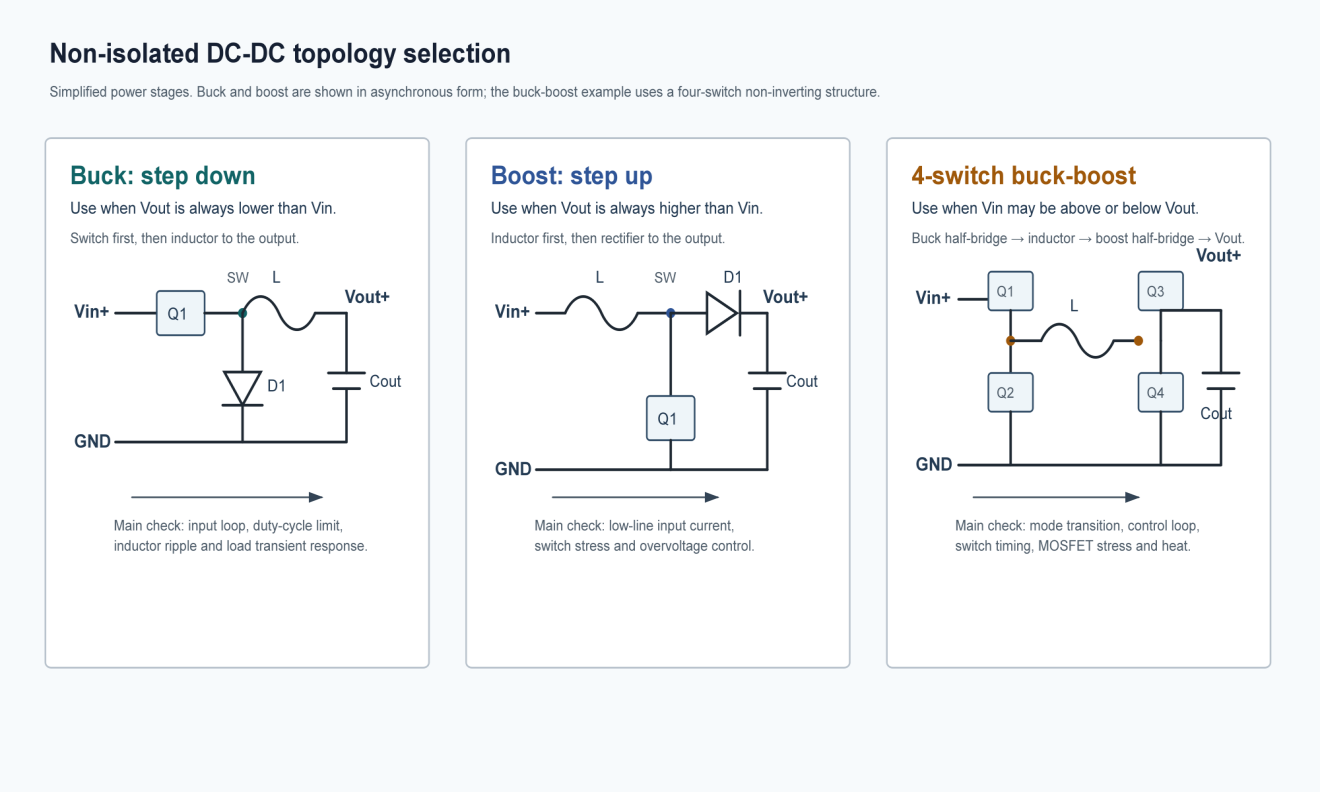
After the basic topology is clear, choose the implementation level. A discrete PWM controller offers flexibility for unusual voltage, current, sequencing, or protection needs. An integrated regulator with internal MOSFETs reduces design time and board area for mainstream loads. A power module can be attractive when the schedule is tight, the design team wants a known layout, or the application values validation speed more than the lowest unit cost.
| Non-isolated option | Best fit | Watch carefully |
|---|---|---|
| Buck | Output is always lower than input | Duty-cycle limit, transient response, inductor ripple, high di/dt input loop |
| Boost | Output is always higher than input | High input current at low Vin, output overvoltage protection, rectifier loss, startup behavior |
| Buck-boost | Input may be above or below output | Control-mode transition, efficiency, switch stress, output polarity for inverting versions |
| Integrated regulator | Standard voltage and current range, compact board | Thermal derating, package dissipation, layout guidance from the IC vendor |
| Power module | Fast development, small engineering team, repeatable layout | Unit cost, sourcing continuity, thermal path, customization limits |
When isolation changes the decision
Isolation changes both the circuit and the responsibility of the design. The transformer is no longer only an energy-transfer component. It also sets safety spacing, leakage behavior, parasitic coupling, mechanical height, temperature rise, and part-to-part repeatability.
Use isolated topologies when the output must be separated from hazardous voltage, when the system has different ground domains, when common-mode noise needs control, or when compliance standards require reinforced or functional isolation. AC-DC power supplies normally use isolated topologies after input rectification and filtering. Some DC-DC converters also require isolation in telecom, rail, medical, instrumentation, and industrial control systems.
The common early choices are flyback, forward, half bridge, and full bridge. The power ranges below are practical starting points. Real designs can cross these boundaries depending on input voltage, switching frequency, cooling, transformer design, semiconductor choice, and cost target.
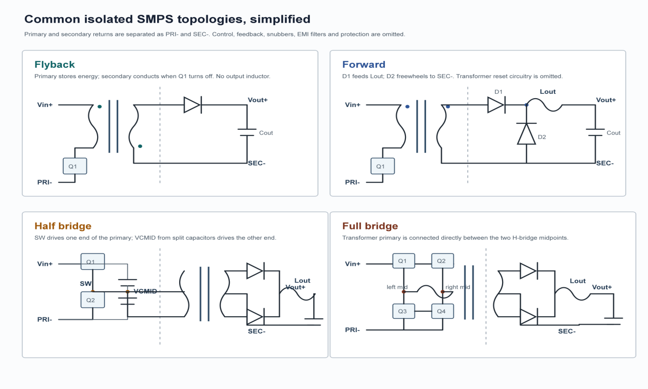
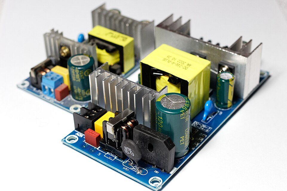
Flyback is usually the first candidate for low-power isolated supplies. It uses the transformer more like coupled inductors, storing energy during the switch on-time and delivering it to the secondary during off-time. Its appeal is clear: low part count, wide input compatibility, and a relatively simple control structure. In many practical designs below about 100 W, a flyback supply can deliver acceptable cost and performance. Efficiency often lands in a broad range because it depends heavily on clamp design, transformer losses, rectification method, input voltage, and load point.
Forward converters suit many medium-power designs. Unlike flyback, a forward converter transfers energy to the secondary while the primary switch is on. This can reduce peak currents and improve transformer utilization, but the transformer needs a reset or demagnetizing path. That extra circuitry raises cost and layout complexity. For many 100 W to 500 W projects, especially where regulation, ripple, and efficiency matter more than minimum BOM count, forward topology deserves a serious look.
Half-bridge topologies become attractive near the upper end of medium power. They reduce voltage stress compared with some single-switch approaches and can support good efficiency, but they need more careful gate drive, transformer design, dead-time control, and layout symmetry. A half bridge is rarely chosen because it is simpler. It is chosen because the power level, thermal target, and efficiency requirement justify the complexity.
Full bridge is commonly considered for higher-power isolated conversion, often above roughly 500 W. Four active switches add cost and control work, but the topology can use the transformer effectively and manage higher power with strong efficiency potential. In industrial supplies, telecom equipment, chargers, and high-power DC systems, full bridge or phase-shifted full bridge designs may be worth the extra engineering effort.
| Isolated topology | Typical early power range | Main advantage | Main tradeoff |
|---|---|---|---|
| Flyback | Below about 100 W | Low cost and low part count | Higher peak currents, transformer stress, EMI and ripple challenges at higher power |
| Forward | About 100 W to 500 W | Better medium-power performance than flyback | Requires reset path and more magnetics/control work |
| Half bridge | Medium to upper range, often near 500 W | Good efficiency potential with lower switch stress | More switches, gate-drive complexity, careful layout required |
| Full bridge | Often above 500 W | Strong high-power capability and transformer utilization | Highest cost and control complexity among these common options |
Efficiency, cost, and size pull against each other
Topology selection is a tradeoff, not a ranking chart.
Higher efficiency often needs lower conduction loss, better magnetics, synchronous rectification, lower switching loss, and a topology that spreads stress across devices. Those choices can increase BOM cost and layout sensitivity. Smaller size may push the switching frequency higher, which can shrink magnetics but raise switching loss and EMI. Lower cost may reduce component count, but it can also leave less margin for thermal stress, hold-up time, surge tolerance, or production variation.
This is where B2B buyers should be careful with simple comparisons. A supplier may offer two 24 V, 150 W supplies with similar datasheet output ratings. One may use a topology and component set that performs well at full load in a ventilated cabinet. Another may run close to its thermal limit in a sealed enclosure. The topology will not tell the whole story, but it gives the buyer a useful way to ask better questions.
Ask about full-load efficiency across the input range, not only one typical number. Ask for derating curves. Ask what happens during overload, short circuit, startup into capacitive load, and high ambient operation. For isolated designs, ask how the transformer is controlled between lots. In repeated industrial purchasing, these details matter more than a neat topology label.
Thermal and EMC concerns should be part of topology choice
Many topology mistakes show up later as heat or EMC problems.
For heat, look at where loss will concentrate. In a low-voltage, high-current output, rectifier loss may dominate unless synchronous rectification is used. In a wide-input flyback, the MOSFET and clamp may carry high stress at certain line conditions. In a compact buck converter, the regulator IC package may be the thermal bottleneck even when the inductor looks comfortable.
EMC is similar. A topology with high peak current, fast voltage transitions, or large hot loops will need disciplined PCB layout and filtering. Flyback converters can be economical, but transformer leakage inductance and drain ringing often demand careful clamp or snubber work. Bridge converters can achieve good power handling, but poor gate timing and layout symmetry can create their own noise problems.
Design teams should not wait until the first EMC failure to think about topology. Review loop area, transformer parasitics, grounding, input filter needs, and cable routing while the converter family is still being chosen. The cheapest topology on paper may become expensive if it needs several rounds of emissions fixes.
A practical selection workflow
A simple workflow helps keep the team from jumping straight to a familiar circuit.
First, write the electrical envelope: input range, output rails, current, power, ripple, transient response, hold-up needs, and protection behavior. Then decide whether isolation is mandatory. If no isolation is needed, choose the non-isolated family from the voltage relationship and evaluate discrete, integrated, or module implementation. If isolation is needed, use power level and performance targets to shortlist flyback, forward, half bridge, or full bridge.
Next, test the shortlist against non-electrical constraints. Board size, height limit, expected ambient temperature, cooling method, safety spacing, certification plan, sourcing risk, and production volume can change the answer. A topology that is elegant for a custom engineering project may be wrong for a cost-sensitive product that must ship for ten years.
Finally, review supplier and manufacturing capability. Magnetics design, transformer insulation, winding repeatability, MOSFET sourcing, controller availability, and test coverage are part of the topology decision. A mature flyback supply from an experienced supplier may beat a more sophisticated topology executed poorly.
| Selection step | Decision output | Red flag |
|---|---|---|
| Define input and output envelope | Required voltage conversion and power level | Only nominal voltage is known |
| Decide isolation | Non-isolated or transformer-isolated path | Isolation treated as optional despite safety or grounding requirements |
| Shortlist topology | Buck, boost, buck-boost, flyback, forward, half bridge, or full bridge | Choice based only on what was used in a previous project |
| Check thermal and EMC risk | Required efficiency, cooling, layout, filtering, and transformer controls | No derating curve or EMC plan before prototype |
| Choose implementation route | Discrete controller, integrated regulator, module, or custom supply | Lowest BOM chosen without considering validation and lifetime cost |
What purchasing teams should ask suppliers
Topology language can be useful in supplier discussions if it leads to practical questions.
For a low-power isolated supply, ask whether the design is flyback, whether synchronous rectification is used, and how transformer leakage and clamp temperature are controlled. For medium power, ask whether a forward or bridge-based design is used and how the design behaves at low line and full load. For higher power, ask about switch stress, transformer temperature, efficiency at realistic operating points, and protection behavior.
Do not stop at "What topology is it?" Ask for evidence. A supplier should be able to provide efficiency data, thermal rise data, derating curves, safety certification information, EMC test status, and mechanical drawings. For industrial use, long-term availability and lot consistency are just as important as the first sample working on the bench.
If the product will be installed in a control cabinet, machine, LED system, charger, or communication device, share the real installation conditions. Cable length, enclosure temperature, peak load, duty cycle, and grounding arrangement can all change the preferred topology or the required derating.
Conclusion
The right power supply topology starts with the job the supply must do. Voltage relationship points toward buck, boost, or buck-boost in non-isolated DC-DC designs. Isolation, safety, and power level move the discussion toward flyback, forward, half-bridge, or full-bridge converters. From there, efficiency, cost, size, thermal design, EMC, supplier capability, and production repeatability decide whether the choice can survive real use.
For OEM and industrial buyers, topology selection is also a supplier-evaluation tool. It helps separate a power supply that merely meets a headline voltage and wattage from one that fits the operating environment. SIPURUI supports switching power supply selection for industrial control, equipment, LED, and automation applications, with practical attention to voltage range, protection, thermal margin, and long-term supply needs.
Buyer Checklist
- Define input range, output rails, current, power, ripple, transient response and protection behavior before choosing a circuit.
- Decide whether isolation is mandatory because safety, ground domains and compliance can change the whole topology family.
- Compare efficiency, cost, size, thermal limits and EMC risk instead of treating topology names as a ranking chart.
- Ask suppliers for efficiency data, thermal rise data, derating curves, certification information, EMC status and mechanical drawings.