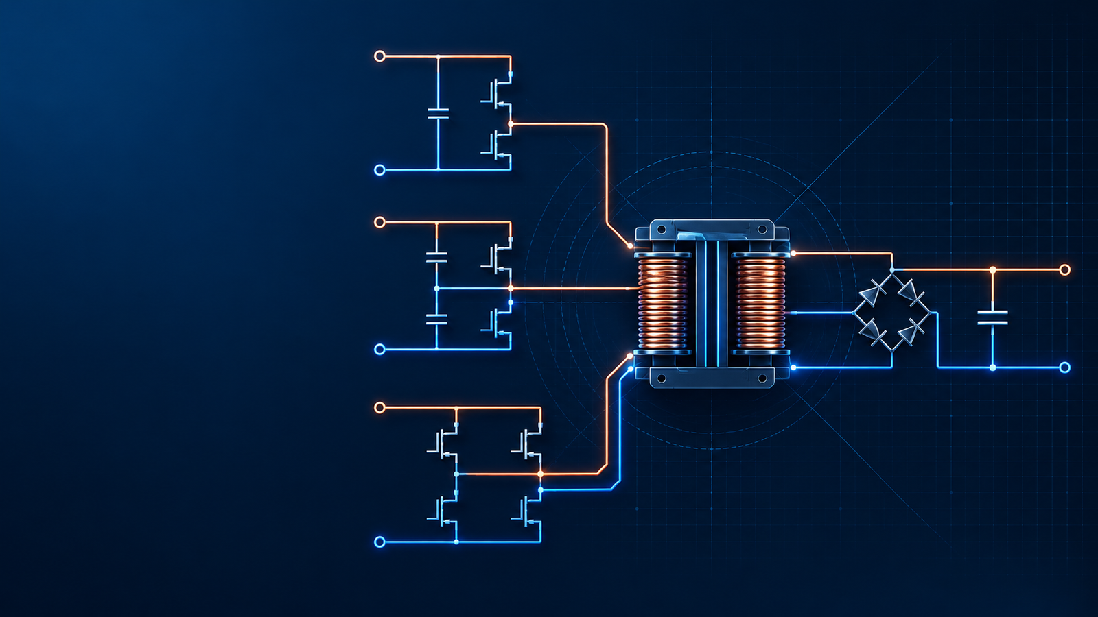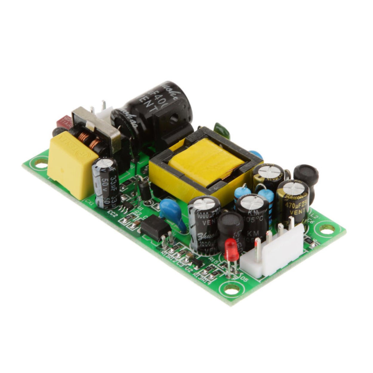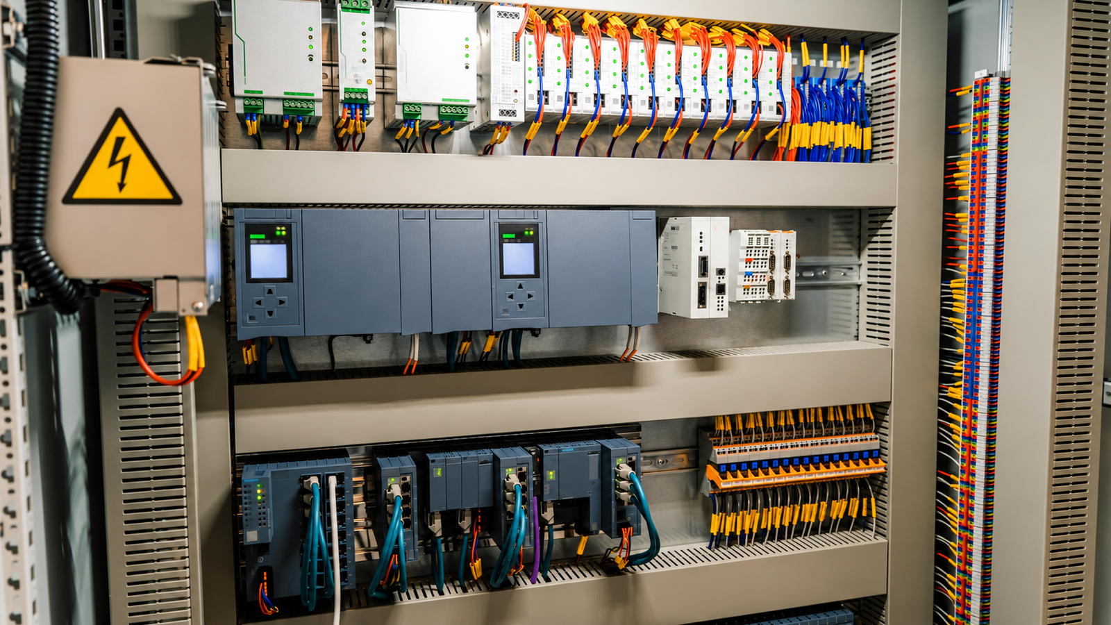
Understand key switching power supply specifications, including line regulation, load regulation, ripple, inrush current, protection, drift, response time, EMC and safety.
Overview
A switching power supply datasheet can look simple until a project depends on it. The headline voltage and current may be correct, but the real decision sits in smaller lines: line regulation, load regulation, ripple and noise, inrush current, overcurrent behavior, leakage current, safety spacing, temperature drift and dynamic response.
For an engineer, those numbers affect circuit stability and product reliability. For an equipment manufacturer or purchasing team, they affect warranty risk, installation problems, replacement frequency and whether one supply can be used across several markets. This guide explains the common specifications in practical language so a team can read a datasheet, compare suppliers and define acceptance tests with fewer surprises.
Start with the specification map, not with one number
Most power supply specifications are connected. A change in input voltage can shift output voltage, temperature can change regulation accuracy, a short circuit can stress the transformer and switching device, and a measurement setup can make ripple look better or worse than it really is.
That is why a useful review starts with the operating envelope. Define the input range, output voltage, continuous load, peak load, ambient temperature, cabinet airflow, startup condition, expected fault condition and applicable safety or EMC standard. Only then do the individual specifications become meaningful.
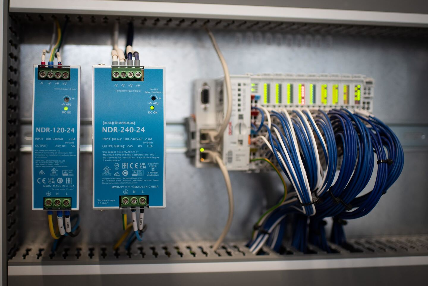
| Specification group | What it tells you | Why it matters in equipment |
|---|---|---|
| Input and line behavior | How the output reacts to input voltage change, surge and input noise | Important for unstable grids, generators, long cable runs and multi-region products |
| Load behavior | How output voltage changes from light load to full load or during load steps | Critical for motors, solenoids, PLC I/O, LED loads and electronics with pulsed current |
| Ripple and noise | The unwanted AC component on the DC output | Affects sensors, communication modules, analog circuits and long-term capacitor stress |
| Protection | How the supply responds to overload, short circuit, overvoltage, undervoltage and overtemperature | Prevents one fault from damaging the supply or the downstream system |
| Safety and insulation | Spacing, dielectric strength, leakage current and insulation resistance | Required for compliance, user safety and international approval |
Line regulation: output stability when the input changes
Line regulation describes how much the DC output changes when the input voltage changes while the load is kept constant. In AC-DC industrial supplies, the input may vary because of grid tolerance, generator operation, long distribution wiring or voltage dips when large machines start. In DC-DC converters, the same issue can come from a battery bus, rectified DC bus or shared intermediate rail.
You may see this specification shown as an absolute voltage change, such as +/-20 mV, or as a percentage of rated output voltage. Some older technical notes describe an absolute regulation coefficient as the ratio between output voltage change and input voltage change. In day-to-day purchasing and test work, the datasheet line regulation percentage is usually easier to compare.
Good line regulation is useful, but it should not be read alone. Check the input range used for the test, the load condition, temperature and whether the value is typical or maximum. A supply that lists excellent regulation only at nominal load may behave differently near no load or close to full load.
Load regulation and output resistance: what happens when the load moves
Load regulation describes the output voltage change when the load current changes, usually from no load or minimum load to rated load, while the input voltage stays at a defined value. It is sometimes called current regulation in older material.
This number is especially important when one supply powers mixed loads. A 24 V rail may feed PLC modules, sensors, relay coils and a small HMI. When relays energize or a motor brake releases, the rail should not sag enough to reset sensitive electronics. A supply with tighter load regulation and better transient response gives more room for wiring voltage drop and real installation variation.
Output resistance is another way to express the same behavior. It is the apparent internal resistance seen at the output: output voltage change divided by load current change. A lower equivalent output resistance means the output voltage is less affected by load current.
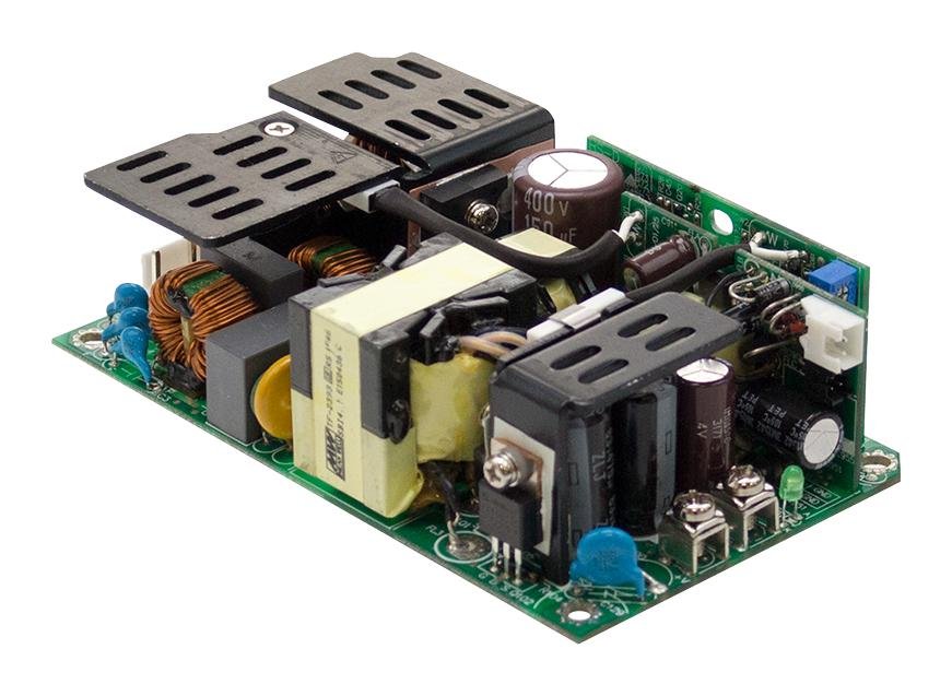
| Condition to compare | Useful question | What to check in the datasheet or test |
|---|---|---|
| No load to full load | Does output voltage stay inside the allowed rail tolerance? | Load regulation value, minimum load requirement and voltage adjustment range |
| Sudden load step | Does the output recover quickly without large overshoot or undershoot? | Dynamic response, recovery time, test slew rate and output capacitance limit |
| Capacitive load at startup | Can the supply start without hiccup or repeated restart? | Startup with capacitive loads, overcurrent mode and soft-start behavior |
| Long output wiring | Will voltage drop at the equipment end be acceptable? | Output voltage trim range, sense function if available and cable current |
Ripple and noise: small numbers that can cause large field problems
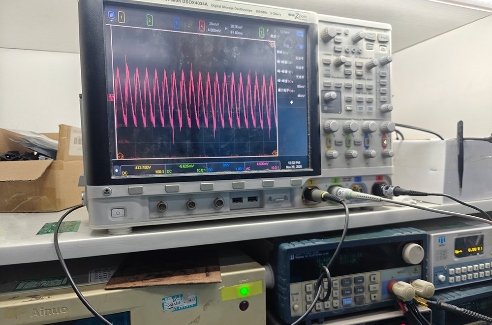
Ripple is the periodic AC component riding on the DC output. It is usually related to mains frequency, switching frequency or the control mode of the converter. Noise is the higher-frequency component that includes switching spikes and broadband energy. Many datasheets combine both as "ripple and noise" or PARD, typically stated in millivolts peak-to-peak.
Peak-to-peak values are common because high-frequency spikes matter to downstream electronics. RMS ripple can also appear in some specifications, especially when the concern is heating or overall AC energy. A ripple coefficient expresses ripple RMS voltage as a percentage of the DC output voltage.
Measurement method matters. Long oscilloscope ground leads can exaggerate spikes. Bandwidth limits, probe type, load condition and capacitor placement can all change the result. When comparing suppliers, ask how ripple and noise were measured: bandwidth, probe connection, load percentage, input voltage and whether an external output capacitor was used.
As a practical rule, sensitive analog, RF, medical, test and communication equipment needs more attention to ripple and noise than simple relay or indicator loads. Industrial control systems sit in the middle: a small amount of ripple may be harmless for actuators, but sensors, encoders and communication modules can be less forgiving.
Inrush current and startup behavior
Inrush current is the short peak input current that flows when the supply is first connected. It comes mainly from charging the input capacitors and magnetizing the input stage. For a single supply, a 20 A or 30 A peak may not be a problem. For a cabinet with many supplies or a machine with frequent power cycling, the total inrush can trip breakers, stress contacts or require a different upstream protection plan.
Do not compare inrush current without checking the test condition. The value depends on input voltage, phase angle at turn-on, ambient temperature, input capacitor size and whether the supply uses an NTC thermistor, relay bypass, active inrush limiter or soft-start circuit.
Startup time and hold-up time belong in the same discussion. Startup time tells you how long the output takes to reach regulation after input is applied. Hold-up time tells you how long the output remains in regulation after input is lost. For controls, robotics, communication equipment and process machines, these two numbers can affect sequencing and ride-through behavior.
Protection specifications: what the supply does when something goes wrong
Protection features are easy to list and easy to misunderstand. The useful question is whether the protection behavior fits the equipment, not whether the datasheet simply names the feature.
Overcurrent protection prevents excessive output current from damaging the supply or load. The trip point is often above rated current, commonly around 110 percent to 130 percent in many designs, but the exact value and mode matter. Some supplies use constant current limiting. Some enter hiccup mode. Some latch off and require input power cycling. Each behavior is acceptable in the right application and troublesome in the wrong one.
Overvoltage protection shuts down or clamps the output when voltage rises too high. Older notes often describe OVP thresholds around 130 percent to 150 percent of nominal output, but real products vary. For PLC, sensor and communication rails, confirm the absolute threshold against the maximum voltage rating of the connected devices.
Undervoltage protection or undervoltage alarm behavior matters when a rail collapses slowly. If output drops below a defined level, often expressed as a percentage of nominal voltage, the equipment may need a warning signal or controlled shutdown before logic becomes unpredictable.
Overtemperature protection stops operation when internal temperature exceeds a safe level. In an enclosed cabinet, this is not a substitute for thermal design. It is a last line of defense. A supply that repeatedly enters thermal protection is already being used outside a healthy margin.
| Protection feature | Typical trigger | Buyer or engineer concern |
|---|---|---|
| Overcurrent protection | Output overload or short circuit | Restart mode, fault energy, wiring protection and whether the load can start normally |
| Overvoltage protection | Feedback failure, abnormal regulation or output overshoot | Maximum safe voltage for PLCs, sensors, drives and control electronics |
| Undervoltage alarm/protection | Output sag below a defined level | Avoiding false operation, controller reset or data loss |
| Overtemperature protection | Internal hot spot above safe limit | Cabinet ventilation, derating and ambient temperature margin |
Temperature drift, temperature coefficient and long-term drift
Temperature affects reference circuits, optocouplers, resistors, capacitors, magnetic materials and semiconductor behavior. Temperature drift describes the output voltage change caused by ambient temperature change. It may be expressed as an absolute value per deg C or as a relative percentage per deg C.
Long-term drift is different. It is the slow output change that occurs over time even when input voltage, load and ambient temperature stay stable. High-precision supplies may specify drift over minutes, hours or longer periods. Standard industrial supplies may not publish this level of detail, but aging still matters through electrolytic capacitors, optocouplers and thermal cycling.
For B2B procurement, the practical point is simple: do not judge precision only at room temperature. If the supply will run in a hot cabinet, near a motor drive or outdoors, review the rated operating temperature, derating curve, cooling method and capacitor lifetime. A supply that is acceptable at 25 deg C can be the wrong choice at 55 deg C with limited airflow.
Dynamic response and recovery time
Response time describes how quickly the output reaches a new stable value after a load change. In modern datasheets, this is often shown as transient response: the output voltage overshoot or undershoot during a specified load step, followed by recovery time.
This is one of the most practical numbers for real equipment. Solenoids, communication modules, small motors, LED drivers and control boards do not draw perfectly constant current. If the supply recovers too slowly, the rail may dip enough to reset a controller. If the response is too aggressive or poorly damped, the rail may ring after each load step.
When reviewing transient response, check the load step size, slew rate, input voltage and output capacitor condition. A graph tested from 10 percent to 50 percent load is not the same as a test from 10 percent to 100 percent load with a fast electronic load.
Input noise, surge, static discharge and EMC immunity
Industrial power supplies do not work in a clean laboratory forever. They may sit near contactors, motors, variable frequency drives, welding equipment or long field wiring. Input noise immunity, surge withstand and electrostatic discharge performance describe how the supply handles abnormal disturbances without unsafe failure or loss of function.
Input noise tests often apply pulse-like voltage disturbances on top of the rated input. Surge tests apply higher-energy impulses to check insulation and robustness. ESD tests apply static discharge to accessible surfaces or the enclosure. Exact test levels depend on the product class, standard and installation environment.
For international B2B buyers, ask for the standard, test level and pass criterion behind the words "surge" and "ESD." A product intended for ordinary indoor equipment and a product intended for harsh industrial cabinets may need different immunity levels.
Electrical safety: spacing, dielectric strength, leakage and insulation
Safety specifications are not decorative paperwork. They define whether the product can be used in equipment that may be touched, serviced and shipped across markets.
Important items include clearance and creepage distance between hazardous live circuits and accessible or secondary circuits, dielectric withstand testing between input and output, input and ground, and sometimes line and neutral. Leakage current measures current flowing through protective earth or accessible conductive parts. Insulation resistance checks whether insulation remains sufficiently high under specified test voltage.
Older Chinese reference material may cite standards such as GB 4943-90 and older UL, CSA, VDE or IEC spacing examples. Treat those as historical notes, not as a current compliance claim. For a live product, verify the latest applicable standard for the destination market, the product category, pollution degree, altitude and insulation class.
A practical verification workflow
A good acceptance plan does not need to be complicated, but it should cover more than nominal input and nominal load. Start with rated output voltage and current, then test the operating corners that match the final equipment.
Use calibrated instruments where possible. Record input voltage, output load, ambient temperature, probe setup and measurement bandwidth. If the supply is part of a machine, test it with representative cable lengths and actual downstream loads instead of relying on a resistor bank alone.
| Verification item | Minimum practical check | Release note to keep |
|---|---|---|
| Output voltage and regulation | Measure at low, nominal and high input across representative loads | Voltage range, load current, ambient temperature and meter accuracy |
| Ripple and noise | Measure with short ground connection and defined bandwidth at rated load | Probe method, bandwidth limit and peak-to-peak value |
| Startup and inrush | Start at cold and warm conditions, with expected capacitive load | Breaker/fuse behavior, startup time and any restart events |
| Fault protection | Test overload and short-circuit behavior safely | Protection mode, recovery method and component temperature |
| Thermal margin | Run at worst cabinet temperature and load | Hot spot temperatures, derating assumption and airflow condition |
How to compare suppliers without getting lost in numbers
When two supplies have the same output voltage and current, compare the conditions behind the specifications. A lower ripple number is useful only if the measurement method is comparable. A wider input range is valuable only if the product still meets output, thermal and safety requirements across that range. A protection feature is helpful only if its restart behavior matches the load.
For equipment manufacturers, the best supplier conversation is specific: "We need 24 V DC at 6 A continuous, 9 A peak for 300 ms, 90-264 V AC input, 55 deg C cabinet ambient, no unexpected PLC reset during solenoid switching, and documented surge and safety compliance for export." That gives the power supply manufacturer a real engineering target instead of a vague request for a better price.
Conclusion
Switching power supply specifications are more than datasheet vocabulary. They describe how the supply reacts to input changes, load changes, ripple, faults, heat and safety stress. Reading them as a connected set helps engineers avoid late redesigns and helps B2B buyers compare products on reliability instead of only wattage and price.
For industrial equipment, automation panels, LED systems and electronic devices that need stable AC-DC or DC-DC power, SIPURUI can support model selection, sample review and specification matching for practical application conditions.
Buyer Checklist
- Confirm input range, output voltage, continuous load and peak load.
- Compare regulation, ripple and transient response under matching test conditions.
- Review protection restart behavior, inrush current and hold-up time.
- Check safety, EMC, temperature derating and real installation conditions.