Switching power supply debugging is more than checking output voltage. This guide explains ten common SMPS problems, from transformer saturation and high MOSFET VDS to light-load ripple, VCC cycling, heavy-load startup failure and short-circuit stress.
Overview
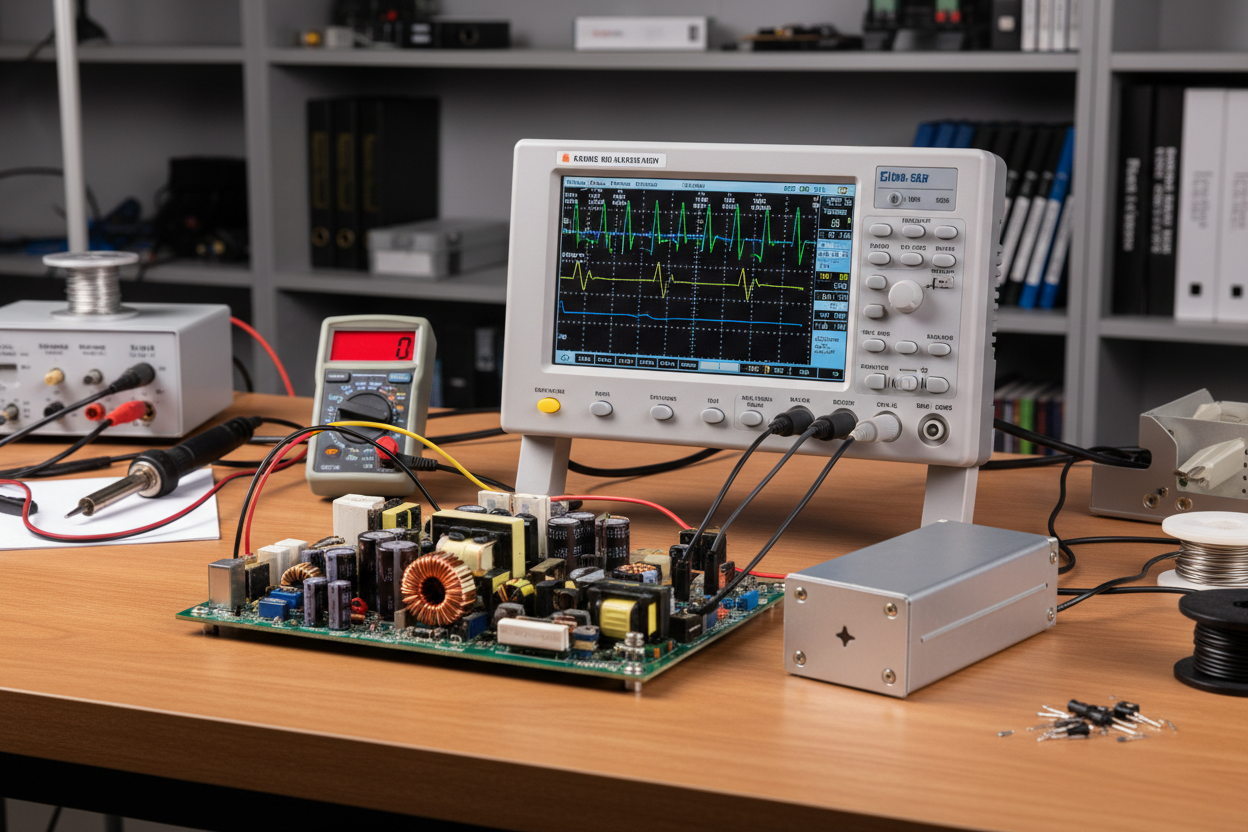
Debugging a switching power supply is rarely a single measurement. A prototype can start normally at nominal input, then fail at low line with a large capacitive load. A unit can pass ripple at room temperature, then overheat the controller in a sealed cabinet. A short-circuit test can look acceptable on the output while the MOSFET drain waveform is already too close to its limit.
This article reorganizes ten common SMPS debugging problems into a practical sequence for engineers, equipment manufacturers, automation integrators and technical buyers who need stable AC-DC or DC-DC power in real equipment. The focus is not theory for its own sake. It is the kind of problem that shows up during bring-up, reliability testing, incoming inspection or field failure analysis.
Before changing parts, define the test corner
Many debugging mistakes start with a test that is too narrow. A supply should be checked across the real input range, load range, ambient temperature, startup condition and fault condition. For industrial supplies, the worst cases usually include high input voltage, low input voltage, maximum load, no load, light load, shorted output, large output capacitance and elevated ambient temperature.
Use the same scope probe setup and current measurement method each time. Keep drain voltage, transformer current, VCC, feedback pin voltage and output ripple in the same capture set whenever possible. When the waveform changes after one component value is adjusted, you need to know which protection loop moved and which stress got worse.
| Test condition | What to watch first | Why it matters |
|---|---|---|
| High-line startup with full load | MOSFET VDS, clamp temperature, primary current | Drain stress and leakage-energy spikes are usually worst here. |
| Low-line startup with heavy or capacitive load | VCC, feedback pin ramp, peak current limit | The supply may run out of startup energy before the output reaches regulation. |
| No load and light load | VCC stability, burst frequency, output ripple | Repeated restart or very low burst frequency often creates visible bounce or ripple. |
| Output short circuit | Pulse count, peak current, VDS spike | Slow protection can keep switching long enough to overheat the MOSFET or clamp. |
| High ambient or enclosed cabinet | Controller case temperature, transformer temperature, electrolytic capacitor temperature | Thermal margin can disappear even when room-temperature electrical tests look clean. |
1. Transformer saturation during startup or fault testing
Transformer saturation shows up as a primary current waveform that stops rising linearly. Instead of a controlled ramp, the current climbs sharply near the end of the switching pulse. Once the core enters saturation, the peak current becomes difficult to predict. The MOSFET, current-sense resistor, transformer winding and clamp network can all see stress beyond the value assumed in the design.
The common causes are familiar: magnetizing inductance too high for the control strategy, too few primary turns, a saturation current lower than the controller's maximum current-limit point, or a startup sequence that lets current rise too fast. The problem often appears at low input during startup, high input during abnormal operation, short circuit, dynamic load or high temperature.
Fix the current envelope first. Lower the controller current-limit point if the design has margin, or strengthen soft-start so the transformer current rises more slowly. If the core still saturates at the required power level, review the transformer turns, core material, air gap and peak flux density. Do not solve a saturation problem only by raising current limit. That may get one startup test to pass while making the short-circuit test dangerous.

2. MOSFET VDS is too high
For a flyback or similar isolated topology, MOSFET VDS stress includes input bus voltage, reflected output voltage and leakage-inductance spike. A good debugging rule is to keep maximum VDS below about 90 percent of the MOSFET rating under the worst test condition. The exact design margin depends on product class and qualification standard, but running close to the rating during startup or short circuit is not a production-friendly choice.
If the flat reflected-voltage level is too high, check the transformer turns ratio. If the spike is the problem, reduce leakage inductance and tune the clamp. Better winding arrangement, shorter high-current loops and controlled insulation spacing can reduce leakage energy. On the circuit side, an RCD clamp, TVS clamp or adjusted snubber can reduce the peak. A slightly slower diode or a damping resistor may also smooth the waveform and help EMI, but every change should be checked for efficiency and temperature.
3. Controller IC temperature is too high
High controller temperature usually comes from one of three places: excessive internal MOSFET loss, weak heat spreading into the PCB, or hot air trapped around the IC. For integrated offline switcher ICs, a large share of heat leaves through the leads and copper area, so the PCB matters more than it may appear in the schematic.
Look at switching loss first. Large transformer parasitic capacitance increases the overlap between MOSFET voltage and current during turn-on and turn-off. More spacing between winding layers, an added insulation layer or a revised winding stack can reduce interwinding capacitance. Then check the copper area connected to thermal pins and high-current pins. In prototypes, added solder can help reveal whether copper area is the limiting factor, but the production PCB still needs real thermal design. Keep the controller away from hot resistors, rectifiers and heatsinks when airflow is limited.
4. No-load or light-load startup failure
One common symptom is VCC repeatedly rising to the startup threshold and falling to the shutdown threshold. The output never reaches stable regulation. At no load or light load, the auxiliary VCC winding may not receive enough reflected energy, so the controller keeps restarting.
Increase the VCC winding turns if the transformer allows it, reduce the VCC current-limit resistor, or add a small preload on the output. After that, check heavy-load operation again. A fix that raises light-load VCC may push heavy-load VCC into the controller's overvoltage protection region. The target is not simply "more VCC." The target is a stable VCC window across the whole load range.
5. The supply starts, but cannot accept heavy load
A supply that starts at light load and fails when load increases often has either VCC overvoltage or current-limit behavior in the wrong place.
At heavy load, the auxiliary winding voltage can rise. If VCC reaches the controller OVP point, the IC shuts down even though the output stage may look capable. If VCC keeps rising past the IC rating, the controller can be damaged. Clamp or regulate VCC, adjust auxiliary turns, and confirm the result at both low line and high line.
The other cause is internal current limit. If the limit point is too low, the MOSFET current is capped before enough energy reaches the secondary side. Raising the current-limit setting can help, but it also raises fault energy. If the current slope is too steep, a slightly higher primary inductance may reduce peak current, provided the transformer does not approach saturation.
6. Standby input power is too high
High standby power can come from repeated startup, burst mode operating too often, or losses in the startup path. If VCC is not maintained at no load, the IC may repeatedly charge the VCC capacitor from the high-voltage input. When the startup pin uses a resistor from the bulk bus, that resistor can dissipate noticeable power during each restart.
If the IC has burst mode but standby power is still high, check burst frequency and feedback behavior. A feedback network that reacts too quickly can pull the controller out of low-power operation too often. Slowing the feedback response can reduce switching events, but do not go so far that load-step response becomes sloppy.
7. Short-circuit input power is too high
During an output short, the worst result is not always "no output." The real risk is that the primary side keeps producing large current pulses for too long. Each pulse stores energy in leakage inductance, and that energy becomes a drain-voltage spike when the MOSFET turns off. The input power rises, VDS rises and the clamp overheats.
Some controllers stop switching quickly when an OCP condition is detected at the feedback pin. Others first hit internal current limit, reduce duty cycle and then wait for VCC to fall to UVLO. The second behavior can allow many more switching pulses before shutdown.
Reduce the number of pulses during a short. The feedback pin should rise fast enough to trigger OCP, so avoid an unnecessarily large feedback capacitor. Then reduce peak current where possible. After every change, repeat the short-circuit test at high input and high ambient because this is often where the MOSFET and clamp have the least forgiveness.
8. No-load or light-load ripple is too large
Light-load ripple is often tied to VCC or burst mode. If VCC oscillates between startup and shutdown thresholds, the converter delivers energy in short bursts and then stops for a long pause. The output capacitor must carry the load through that pause. If it cannot, the output voltage sags and the ripple looks much larger than expected.
If VCC is stable but ripple is still high, check burst frequency. A very low burst frequency can make the output voltage visibly move, especially with small output capacitance or sensitive downstream electronics. A slightly higher burst frequency or larger output capacitor can help, as long as standby input power remains within the product requirement.
9. Heavy-load or capacitive-load startup fails
Large output capacitance changes the startup problem. For example, a 10,000 uF output capacitor charged to 5 V stores 0.125 J of energy. That number looks small, but the supply must deliver it within the required startup time while also feeding the load and staying below protection thresholds.
If the output voltage rises too slowly, the optocoupler may remain weakly driven. The controller's feedback pin can then charge toward the OCP threshold before the output has reached regulation. The MOSFET turns off, the output collapses and the supply never starts.
There are several practical fixes. Increase the peak current limit only after checking transformer saturation at low input. Shape the feedback pin ramp so it rises more slowly during startup. A larger feedback capacitor can help, but too much capacitance worsens normal transient response and may increase ripple. A capacitor and Zener network on the feedback pin can delay the later part of the ramp without disturbing normal low-voltage behavior. Another useful method is adding a capacitor across the TL431 cathode-anode path, so startup feedback current through the optocoupler keeps the feedback pin under control for longer. The RC timing must be checked against the required output rise time.
| Symptom during startup | Likely electrical cause | Practical correction |
|---|---|---|
| VCC cycles between startup and UVLO | Auxiliary winding energy is too low | Increase VCC turns, reduce VCC resistor, or add a small preload. |
| Output starts at light load but fails at heavy load | Current limit is reached too early or VCC hits OVP | Tune current-limit setting and stabilize VCC across load range. |
| Large capacitive load cannot start | Feedback pin reaches OCP before output reaches regulation | Slow the VFB ramp, review TL431/optocoupler startup path, and verify transformer margin. |
| MOSFET gets hot during repeated startup | Too many restart pulses or high peak current | Strengthen soft-start, reduce pulse count and check clamp dissipation. |
10. Output voltage rebounds after input is turned off
At no load or light load, the output can fall after AC input is removed and then jump up again. This rebound happens because the bulk capacitor on the primary side still holds enough voltage to feed the high-voltage startup pin. The IC restarts briefly, transfers another packet of energy, and the output rises again.
A larger resistor in series with the startup pin can reduce the available startup current as the bulk capacitor decays. Another method is to connect startup before the rectifier bridge, so the startup pin falls quickly when input is removed instead of being held up by the bulk capacitor. This change must be checked against safety, surge and IC application guidance.
A practical debugging checklist
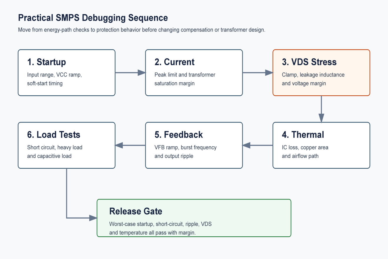
The fastest debugging work usually follows a repeatable order. Start with the energy path, then protection timing, then thermal behavior, then refinement of ripple and standby performance. If you adjust feedback first, you may hide the symptom while leaving the real stress in the transformer or MOSFET.
| Debugging area | Checkpoint | Acceptable direction |
|---|---|---|
| Transformer | Current ramp remains controlled at startup, overload and short circuit | No sudden nonlinear current rise before current limit. |
| MOSFET drain | VDS remains below the chosen derating limit | Spike and plateau are both understood, not just the total peak. |
| VCC | Stable from no load to full load | No repeated restart at light load and no OVP at heavy load. |
| Feedback | OCP timing is fast during fault but slow enough for capacitive startup | Startup ramp and short-circuit response are both verified. |
| Thermal | Controller, transformer, rectifier and clamp stay within limit | Measurements are taken after thermal soak, not just during quick bring-up. |
| Output | Ripple and rebound meet system requirements | Burst mode does not create unacceptable low-frequency ripple. |
What buyers and equipment builders should ask suppliers
For B2B buyers, these ten issues become supplier evaluation questions. Ask whether the power supply has been tested at low line, high line, no load, rated load, short circuit and high ambient temperature. Ask how VDS margin is verified and whether startup has been tested with the real downstream capacitance in your equipment. For industrial cabinets, check whether the datasheet rating assumes free air, forced air or a specific mounting orientation.
SIPURUI can help match switching power supplies to automation cabinets, LED equipment, machinery control systems and other industrial loads where startup behavior, ripple, temperature and protection timing matter in daily operation.
Conclusion
Most SMPS debugging problems are connected. Raising current limit may help a capacitive load start, but it can worsen transformer saturation and short-circuit stress. Increasing a feedback capacitor may delay protection during startup, but it can slow transient response and increase ripple. Reducing VDS spikes may improve reliability, but clamp losses and EMI still need to be measured.
Treat the ten problems as one system: transformer, MOSFET, VCC, feedback loop, thermal path and real load behavior. That approach gives engineers a cleaner prototype bring-up and gives buyers a better way to judge whether a power supply will survive outside the lab.
Buyer Checklist
- Test low line, high line, no load, rated load, short circuit and high ambient conditions.
- Verify MOSFET VDS margin and clamp temperature under worst-case startup and fault tests.
- Confirm VCC stability from light load to heavy load before approving the design.
- Check capacitive-load startup with the real downstream capacitance in the equipment.
- Review ripple, standby power, short-circuit behavior and thermal margin as connected issues.