A switching power supply can appear to fail its ripple specification before anyone has changed the circuit. A long probe ground lead picks up the switch-node field, an unsuitable probe buries a millivolt signal in channel noise, or a full-bandwidth capture is compared with a datasheet value measured at 20 MHz. The resulting waveform looks alarming, yet much of it may belong to the measurement loop rather than the converter output.
Overview
A switching power supply can appear to fail its ripple specification before anyone has changed the circuit. A long probe ground lead picks up the switch-node field, an unsuitable probe buries a millivolt signal in channel noise, or a full-bandwidth capture is compared with a datasheet value measured at 20 MHz. The resulting waveform looks alarming, yet much of it may belong to the measurement loop rather than the converter output.
The practical rule is simple: define the measurement before judging the power supply. Probe connection, bandwidth, coupling, test point, input voltage, load, operating mode, warm-up time, and measurement statistic must match the requirement being verified. This guide explains how to build a repeatable setup, when common rules such as AC coupling and a 20 MHz bandwidth limit apply, and how to separate a probing artifact from a real design problem.
Ripple, switching transients, and broadband noise are not the same thing
Engineers often use “ripple and noise” as one specification, but the visible waveform can contain several mechanisms.
Periodic ripple is correlated with converter operation. In a fixed-frequency PWM converter, its dominant component is commonly at the switching frequency, with harmonics shaped by the output inductor, capacitor network, ESR, control mode, and load current. The claim that ripple frequency always equals one switching frequency is too narrow: multiphase converters, burst mode, pulse skipping, rectified-line energy, beat frequencies, and control-loop behavior can add other periodic components.
Switching transients are narrow spikes or ringing events associated with fast voltage and current edges. Diode reverse recovery, MOSFET transition current, package inductance, PCB parasitics, and the probe loop all affect their apparent amplitude. These events contain far more high-frequency energy than the underlying capacitor ripple.
Broadband noise and coupled interference may come from the converter, nearby equipment, the oscilloscope, or the measurement connection. A random-looking trace is therefore not proof that the regulator is noisy.
Datasheets frequently combine these effects into one peak-to-peak limit under stated conditions. That number is meaningful only when the same bandwidth, connection method, load, and test location are used.
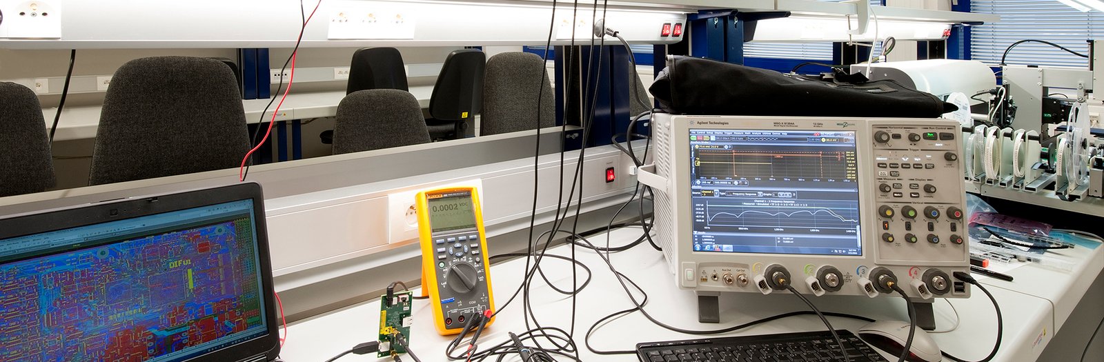
Why the wrong probe connection creates a convincing false failure
A standard probe ground clip can form a loop several centimeters wide. Its inductance develops voltage during fast current transitions, while the loop area couples magnetic and electric fields from the transformer, switch node, rectifier, and hot power loop. The oscilloscope faithfully displays this induced signal, which is why the artifact can look repeatable and “real.”
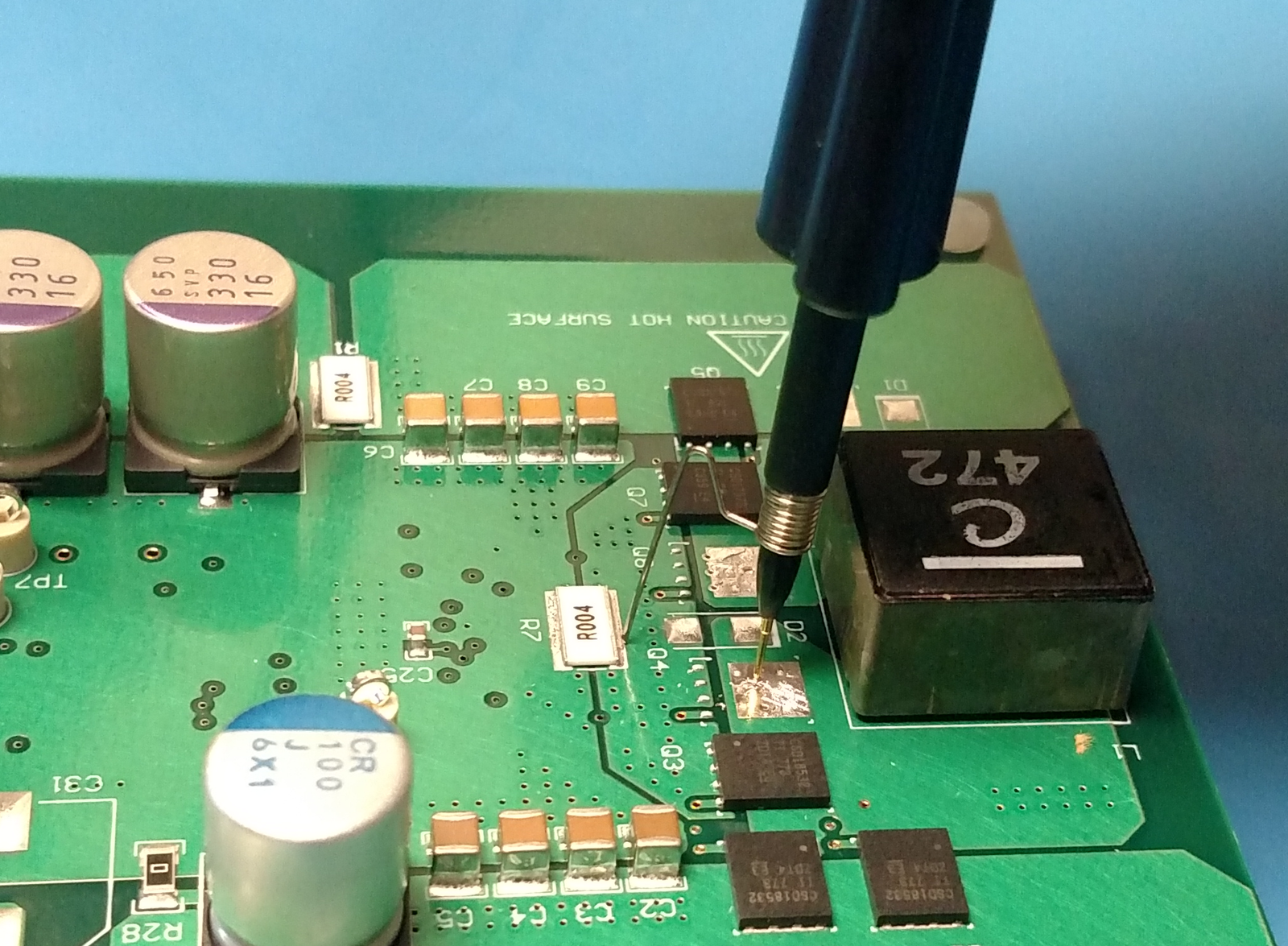
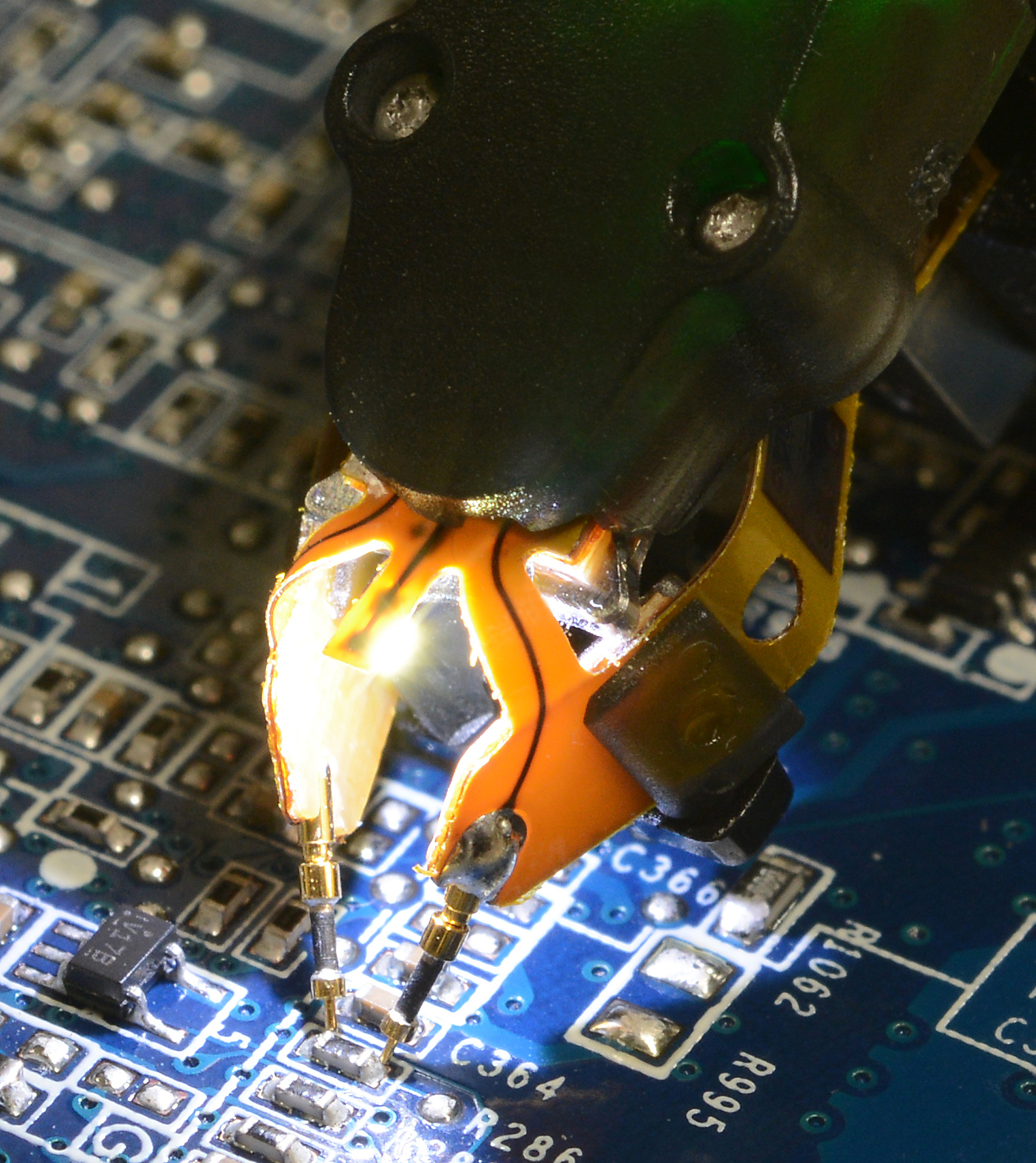
Replace the long ground lead with a ground spring, tip-and-barrel connection, soldered probe socket, or properly terminated coaxial connection. Place the signal and return contacts directly across the intended measurement node. For converter-output characterization, this is usually the output capacitor terminals or a dedicated test point beside them. For system-level power-integrity verification, measure at the load pins or local bypass capacitor as well. These are different questions, so neither location is universally correct.

Six measurement mistakes that distort the result
A long alligator-clip ground lead
This is the most common source of false spikes. The error cannot be expressed as a universal “3x” or “8x” multiplier because it depends on loop geometry, edge rate, field strength, probe position, and bandwidth. A quick diagnostic is to short the probe tip to its own ground connection near the converter. Any displayed switching-correlated signal is pickup or instrument noise, not output ripple.
Treating 1x or 10x as a universal answer
A 10x passive probe attenuates the signal before it reaches the oscilloscope, which can push low-level ripple toward the channel noise floor. A 1x probe can improve vertical sensitivity, but it often has lower bandwidth and higher input capacitance. For small ripple, a short 1x probe, a low-noise active probe, or a 50-ohm coaxial method may be appropriate. For faster transients, a suitable 10x or active probe may be necessary. Choose the probe from the signal amplitude, required bandwidth, source loading, and the datasheet test method.
Using full bandwidth for a 20 MHz specification
Many power-supply datasheets quote ripple and noise with a 20 MHz bandwidth limit. Comparing that limit with a 200 MHz or 1 GHz capture is not an apples-to-apples test. However, full bandwidth is not “wrong”: it is useful when debugging switching spikes, ringing, and local power integrity. Record both views when necessary and label them clearly.
Assuming AC coupling is always mandatory
AC coupling removes the DC output level so the vertical scale can be expanded, making it convenient for millivolt ripple on a multi-volt rail. Check the channel’s AC-coupling corner frequency, settling behavior, and overload limits. DC coupling remains useful when droop, startup, load steps, or slow modulation must be preserved. The coupling choice should follow the phenomenon being measured.
Measuring at an undefined location
The output capacitor, supply connector, cable end, and IC power pins can show different waveforms because trace and cable impedance convert load current into voltage variation. State the location explicitly. A product acceptance test should follow the supplier’s specified point; a system-debug test should include the point of load.
Changing load, line, or operating mode during comparison
Ripple depends on input voltage, load current, temperature, switching mode, and control strategy. Burst or pulse-skipping operation at light load may produce a larger low-frequency envelope than fixed-frequency PWM. Do not disable these modes simply to make the trace look tidy unless the requirement calls for forced PWM. Instead, test the operating points the product will actually encounter.
Correct and incorrect setup choices
| Measurement element | Common mistake | Repeatable practice | Why it matters |
|---|---|---|---|
| Probe return | Long flying ground lead | Ground spring, probe socket, or short coaxial connection | Minimizes pickup and loop inductance |
| Probe attenuation | Always use 10x or always use 1x | Select for signal level, bandwidth, loading, and noise floor | Prevents loss of resolution or excessive capacitive loading |
| Bandwidth | Compare full-bandwidth data with a 20 MHz limit | Match the published limit; use a second full-bandwidth capture for debug | Separates compliance comparison from transient investigation |
| Coupling | Use AC or DC by habit | AC for small steady ripple; DC for droop, startup, and slow behavior | Preserves the information required by the test |
| Test location | Probe wherever access is convenient | Define output-capacitor and/or point-of-load measurement | Makes results reproducible and relevant |
| Operating point | Record an unstable or unspecified condition | Document line, load, temperature, mode, warm-up, and remote sense | Allows valid comparison between builds and suppliers |
| Statistic | Quote an unlabeled automatic value | Record peak-to-peak method, acquisition mode, time span, and sample count | Avoids misleading extrema and inconsistent reports |
A repeatable bench procedure
1. Start with the requirement, not the oscilloscope
Read the converter or power-module datasheet and the system acceptance plan. Capture the specified input voltage, load range, ambient or case temperature, bandwidth, probe method, output capacitor, and measurement location. If the vendor does not define these conditions, create an internal method and use it consistently; do not present it as an industry-wide standard.
2. Establish a safe measurement reference
Confirm whether the output is isolated and whether its return may be connected to protective earth through a grounded oscilloscope. Never clip a ground-referenced probe to a high-side switching node or non-isolated primary circuit. Use a correctly rated differential probe or an isolated measurement system where required. Do not defeat the oscilloscope protective-earth connection.
3. Configure the signal path
Begin with the bandwidth and coupling defined by the specification. For a typical low-level steady-state ripple comparison, 20 MHz bandwidth limiting and AC coupling are common. Use adequate sample rate and record length, disable display smoothing that hides peaks, and avoid averaging unless the procedure explicitly permits it. Averaging can remove asynchronous noise and make a failing trace appear better than a single-shot acquisition.
Set the vertical scale so the ripple occupies a useful portion of the display without clipping. Check the channel noise by shorting the measurement input in the same configuration.
4. Make the smallest practical loop
Probe directly across the output capacitor or dedicated test pads using a ground spring, probe socket, or coaxial connector. Keep the probe body and cable away from the switch node and transformer. Repeat the measurement after rotating or moving the probe slightly: a large change suggests field pickup.
5. Stabilize and document the operating point
Allow the unit to reach thermal stability appropriate to the product. Record AC or DC input, output voltage, load current, ambient temperature, cooling, control mode, switching frequency if fixed, and any remote-sense connection. Test nominal conditions plus the line/load corners required by the specification. Full load alone is not sufficient for products that enter burst mode or change frequency at light load.
6. Capture two complementary views when debugging
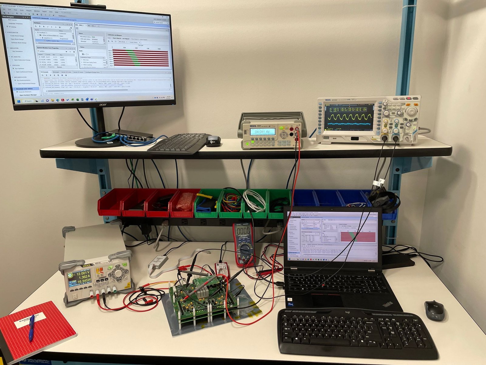
Use the specification bandwidth for the pass/fail comparison. Then take a full-bandwidth or higher-bandwidth view with a suitable probe when investigating narrow transients or ringing. A third capture over a longer time span can reveal burst envelopes, beat frequencies, or rectified-line ripple that a microsecond-scale view misses.
7. Report the result with context
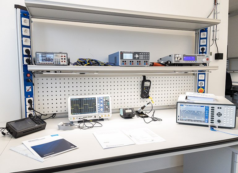
Include a waveform screenshot and a setup photo or diagram. State the instrument, probe, attenuation, termination, bandwidth, coupling, acquisition mode, timebase, vertical scale, test point, input, load, temperature, and operating mode. Peak-to-peak voltage is common for ripple-and-noise limits, but automatic peak-to-peak measurements can be sensitive to rare events and record length. If a limit depends on a defined observation window or statistical method, follow it exactly.
How to interpret a waveform after the setup is trustworthy
| Observed pattern | Likely causes to investigate | Useful confirmation |
|---|---|---|
| Periodic ripple at switching frequency is high | Output capacitance, capacitor ESR/ESL, inductor ripple current, topology, load | Compare against calculated ripple; probe directly across output capacitor |
| Narrow spike synchronized to switch edges | Real switching transient, probe-loop pickup, common-mode coupling, diode recovery, layout inductance | Short-input pickup test; short-loop or coaxial measurement; compare bandwidths |
| Damped ringing after each transition | Parasitic LC network, package/trace inductance, rectifier or MOSFET transition | Measure ringing frequency; inspect hot-loop layout; evaluate snubber with loss checks |
| Low-frequency envelope at light load | Burst mode, pulse skipping, hysteretic control, minimum-load behavior | Correlate with switch-node activity and load current; test forced PWM if supported |
| 100/120 Hz component | Rectified-line energy, insufficient hold-up capacitance, control-loop feedthrough | Change line voltage and load; examine bulk-capacitor ripple |
| Random trace that changes when the probe moves | Radiated pickup, poor ground connection, nearby equipment | Reposition probe and cable; short the probe locally; turn nearby sources off one at a time |
| Droop or overshoot during a load step | Output impedance, control-loop bandwidth, current limit, remote-sense path | Use DC coupling and a synchronized load-current trace |
Correct the mechanism, not the screenshot
Once the measurement artifact has been removed, the waveform can guide design work. Excess periodic ripple may call for a different output capacitor network, lower ESR at the relevant frequency, adjusted inductance, or a change in switching mode. High-frequency spikes often respond better to reduced hot-loop area, lower parasitic inductance, controlled edge rate, appropriate rectifier selection, or a carefully designed snubber than to indiscriminate bulk capacitance.
Any RC snubber or added capacitor changes dissipation, loop behavior, inrush, component stress, and EMI. Verify efficiency, temperature rise, stability, startup, load transient response, and conducted/radiated emissions after the modification. A prettier oscilloscope trace is not sufficient evidence of a better power supply.
Acceptance checklist for engineering and purchasing teams
| Check | Evidence to retain |
|---|---|
| Test method matches the datasheet or agreed internal procedure | Procedure revision and supplier specification |
| Probe connection has minimal loop area | Setup photograph showing signal and return contacts |
| Bandwidth and coupling are stated | Oscilloscope screenshot with channel settings |
| Input, load, temperature, and mode are controlled | Bench log or automated test record |
| Measurement point is unambiguous | PCB image, drawing, or test-point identifier |
| Both pass/fail and debug captures are labeled | Separate 20 MHz and full-bandwidth files where applicable |
| Retest follows any circuit change | Before/after waveforms plus efficiency and thermal results |
Final takeaway
Accurate ripple testing is not a matter of making one oscilloscope setting mandatory. It is a controlled comparison between a defined requirement and a documented measurement. Minimize the probe loop, match the specified bandwidth, choose the probe and coupling for the signal, measure at the location relevant to the decision, and hold the operating point steady.
For OEM and automation projects, SIPURUI can help buyers define output-ripple acceptance conditions alongside line/load range, thermal limits, protection behavior, and EMC requirements. A shared test method prevents avoidable supplier disputes and makes sample approval more meaningful.