Choosing an EMI filter for a switching power supply starts with identifying whether the dominant interference is common-mode, differential-mode, or mixed. This guide explains how to select chokes, X/Y capacitors, ratings, layout, and test methods for practical EMC performance.
Overview
A switching power supply can pass functional tests and still fail in the field because of electromagnetic interference. The output voltage looks stable, the load turns on, and the product ships. Then a control cabinet starts tripping sensors, a communication module loses packets, or an EMC lab report shows conducted emissions above the limit line.
That is where the EMI filter becomes more than a small group of inductors and capacitors near the input terminal. It is part of the power supply's reliability story. For equipment manufacturers, automation integrators, and industrial buyers, the question is not simply "Does this power supply have a filter?" The better question is: "Does the filter match the noise path, the installation, the current rating, the safety requirement, and the EMC target?"
This guide explains how to select a suitable EMI filter for a switching power supply without turning the decision into a lab-only exercise. The goal is practical: understand what type of noise you are fighting, choose the right filter structure, check the ratings that matter, and avoid common mistakes that make an otherwise good filter ineffective.
Start by separating common-mode and differential-mode noise
Switching converters create noise through fast voltage and current transitions. MOSFET switching edges, transformer leakage inductance, rectifier recovery, parasitic capacitance, PCB loops, and long input or output cables can all become part of the EMI path. Before choosing a filter, identify whether the dominant problem is differential-mode noise, common-mode noise, or a mixture of both.
Differential-mode noise flows between the two power conductors. On an AC input, that means line to neutral. On a DC input or output, it means positive to negative. The noise current goes out on one conductor and returns on the other. It often appears as ripple or high-frequency voltage across the input or output terminals.
Common-mode noise flows in the same direction on both conductors and returns through chassis, protective earth, cable shields, nearby metalwork, or parasitic capacitance. It is strongly linked to radiated emissions and to conducted-emissions failures in the 150 kHz to 30 MHz range used by many EMC standards.
In a serious design or compliance investigation, use measurement equipment rather than guessing. A spectrum analyzer or EMI receiver with a LISN can show the frequency and amplitude of conducted emissions. A current probe can help separate common-mode and differential-mode current by clamping around both conductors together or by arranging the conductors so differential components are emphasized. Even a basic pre-compliance setup can prevent expensive trial-and-error changes later.
For many industrial power supplies, the dominant conducted noise is not fixed across the whole spectrum. A design may show differential-mode energy near the switching frequency and lower harmonics, then common-mode energy becomes more visible at higher frequencies. That is why a practical EMI filter usually combines more than one element.
Match the filter topology to the noise path
An EMI filter is usually built from a few familiar parts: common-mode chokes, differential-mode inductors, X capacitors, Y capacitors, sometimes ferrites, and often protection parts such as fuses, MOVs, or NTC thermistors nearby. The function of each part depends on where it sits and which noise current it is meant to block or bypass.
For differential-mode noise, the classic structure is a low-pass filter between the two conductors. A differential-mode inductor or the leakage inductance of a common-mode choke adds series impedance. An X capacitor across line and neutral, or across DC positive and negative, provides a low-impedance path for high-frequency noise to circulate locally instead of returning to the power source.
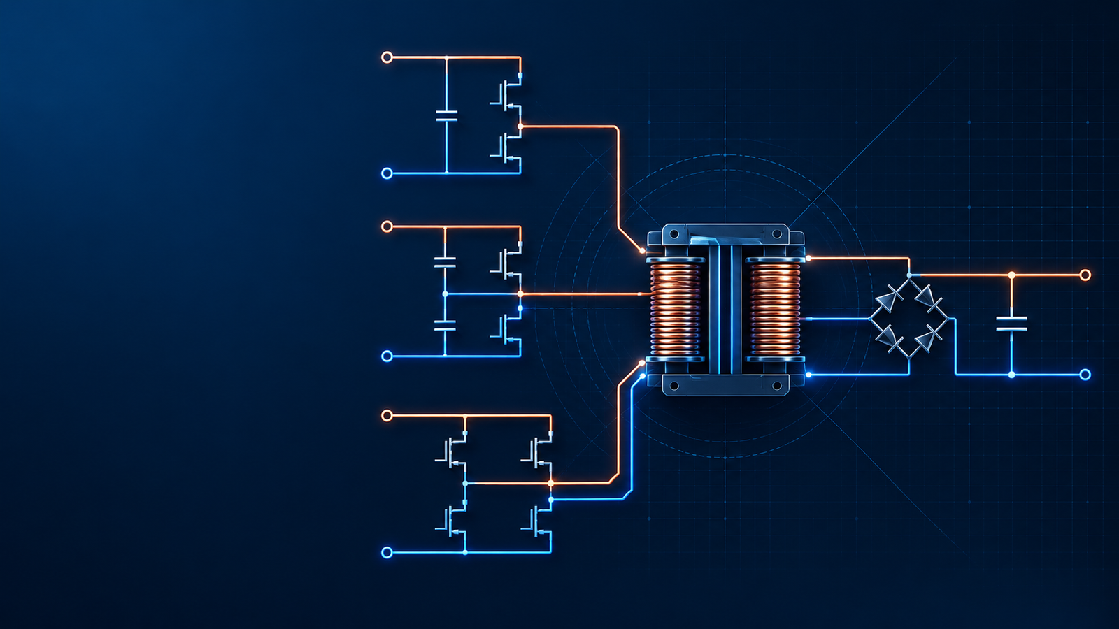
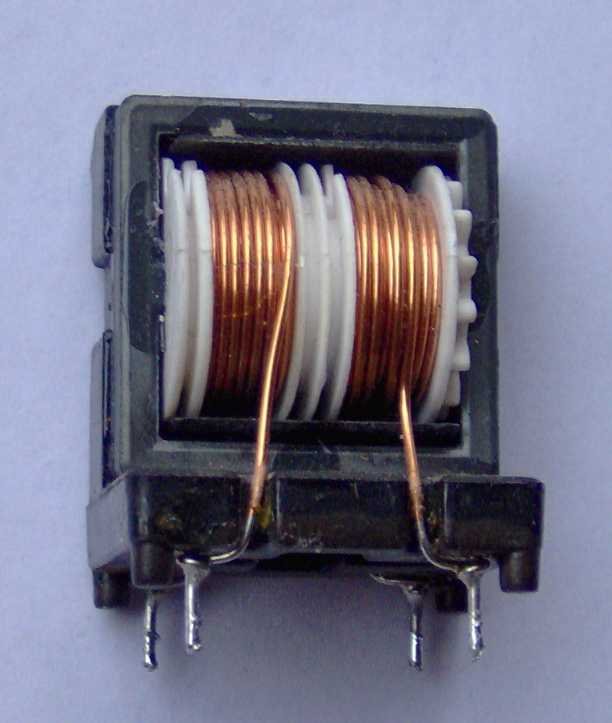
For common-mode noise, the core part is the common-mode choke. Its two windings share one magnetic core. Normal load current flows in opposite magnetic directions and largely cancels inside the core, so the choke can carry the working current with relatively low loss. Common-mode current flows in the same magnetic direction in both windings, so the flux adds and the choke presents high impedance to that unwanted current. Y capacitors then provide a controlled high-frequency return path to protective earth, chassis, or the appropriate reference point.
The table below gives a practical starting point.
| Noise or requirement | Typical filter element | What to check before selecting |
|---|---|---|
| Differential-mode noise between input lines | Differential-mode inductor plus X capacitor | Rated current, saturation current, DCR, capacitor safety class, resonant behavior |
| Common-mode noise to chassis or earth | Common-mode choke plus Y capacitors | Current rating, impedance curve, leakage current, insulation and safety approvals |
| Output ripple seen by a sensitive load | Output LC or pi filter near the load | Load transient response, voltage drop, stability, capacitor ripple current |
| High-frequency cable radiation | Common-mode choke, ferrite core, shield bonding | Cable length, grounding method, frequency range, temperature rise |
| Surge or mains transient exposure | MOV, TVS, fuse, NTC, coordinated input filter | Voltage rating, energy rating, fuse coordination, safety standard requirements |
Do not treat the filter as an isolated accessory. The wiring, chassis connection, PCB layout, safety earth, and enclosure all decide whether the filter has a low-impedance path for the noise it is trying to control.
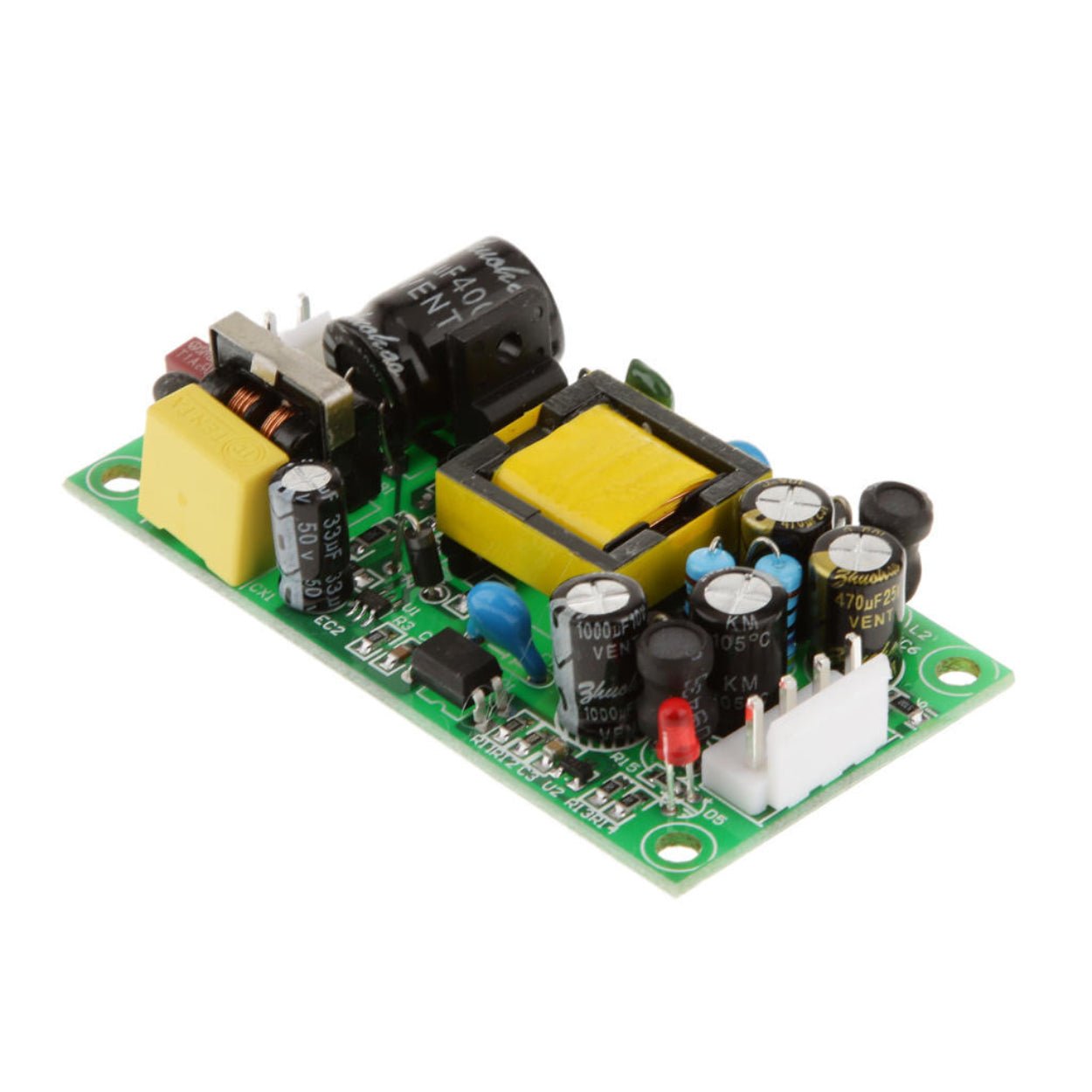
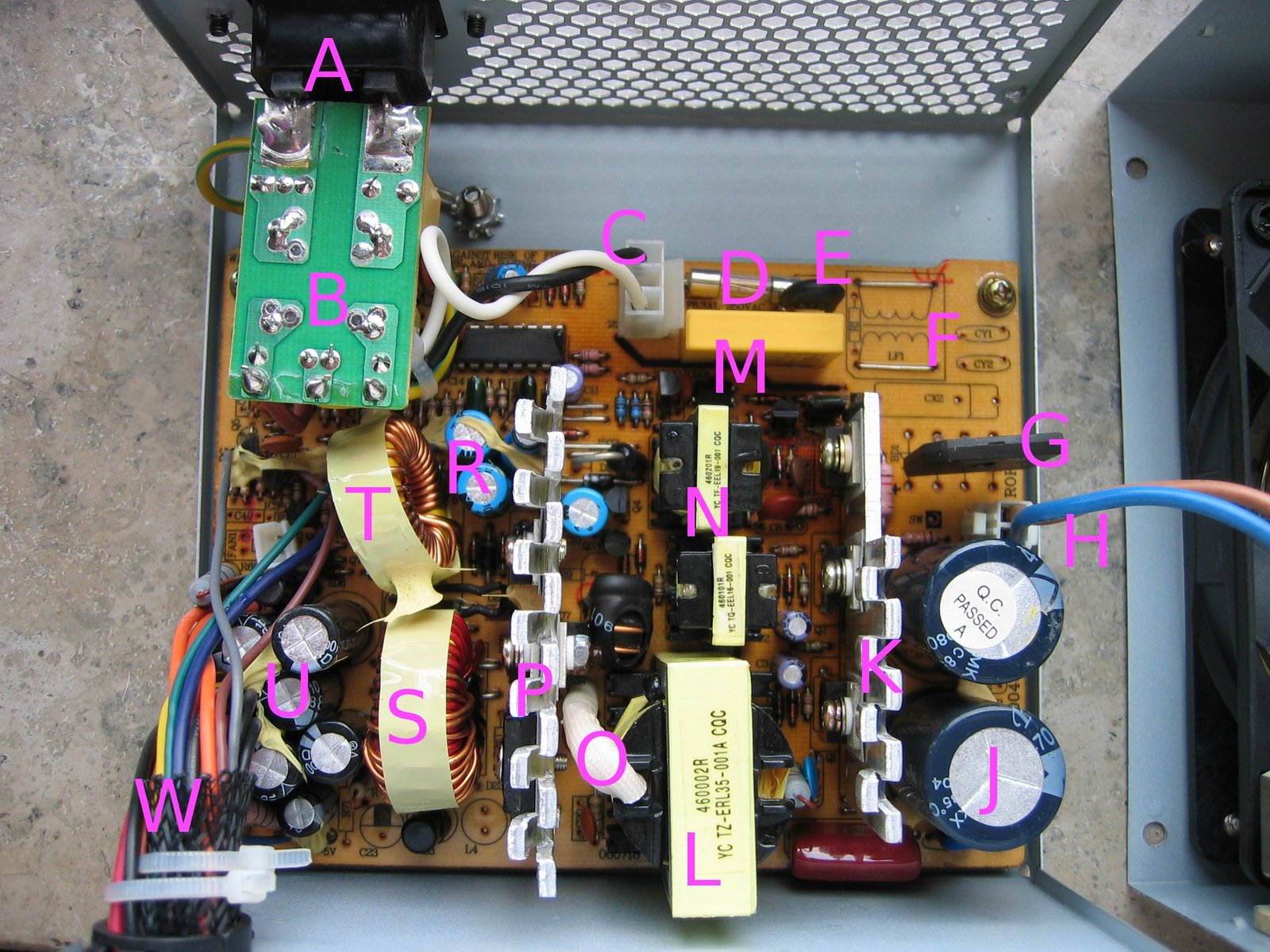
Caption: The input side of an AC-DC power supply typically combines filtering and protection parts. In industrial supplies, the same design logic must be adapted to the enclosure, grounding scheme, and compliance target. Source: Wikimedia Commons, author Hans Haase, CC BY-SA 3.0.
Choose inductance by impedance, current, and frequency
It is tempting to choose the largest choke that fits the enclosure. That can backfire. Inductance is only one part of the decision. You need to look at the impedance curve across the problem frequency range, the rated current, temperature rise, DC resistance, and saturation behavior.
For a differential-mode inductor, the working current passes through the winding directly. The part must tolerate the maximum continuous input or output current without overheating, and the saturation current should be high enough for normal operating conditions. Low DCR matters because any series resistance becomes heat and voltage drop. In small power supplies below roughly 100 W, differential inductance may sit in the hundreds of microhenries to low millihenries range, but the real value depends on the measured noise frequency, converter topology, current, and allowable loss.
For a common-mode choke, the normal differential load current mostly cancels magnetically, so the common-mode inductance can be much higher than a single series differential inductor of similar current rating. Typical power common-mode chokes can range from fractions of a millihenry to tens of millihenries. Higher inductance is useful at lower EMI frequencies, but the part's impedance at high frequency may be limited by winding capacitance and core behavior. Always review the impedance-versus-frequency plot, not only the inductance printed in the catalog.
Core material also matters. Ferrite chokes are common and cost-effective for many SMPS filters. Nanocrystalline cores can offer high impedance in a compact size, especially for higher-current industrial equipment, but they cost more. For buyers evaluating finished power supplies, the practical question is whether the supplier has validated the filter over the relevant current, temperature, and EMC test conditions.
Select X and Y capacitors with safety and leakage in mind
Capacitors often make the filter look simple on paper and complicated in certification. Across-the-line capacitors and line-to-earth capacitors must be safety-rated correctly. Ordinary capacitors are not acceptable in mains-connected EMI filter positions.
An X capacitor is connected across the power lines. In an AC input filter, that means line to neutral. It helps shunt differential-mode noise. Its voltage rating and safety class must match the mains environment and expected transient stress. Larger capacitance lowers high-frequency impedance, but it can also increase inrush behavior, interact with line impedance, and create resonance with inductors.
A Y capacitor is connected from line or neutral to protective earth, chassis, or across an isolation barrier in a controlled way. It helps provide a return path for common-mode noise. The tradeoff is leakage current. If the Y capacitance is too large, the product may fail leakage-current limits or create unwanted touch current. This matters in medical equipment, measurement instruments, building automation products, and other installations where safety and user contact are part of the compliance review.
For industrial AC-DC supplies, Y capacitor values are often in the nanofarad range, not the microfarad range. The correct value depends on the noise level, grounding system, insulation class, applicable standard, and allowed leakage current. For DC-DC converters or floating outputs, the same idea applies, but the reference point and safety barrier need careful review.
| Component | Main EMI role | Practical selection notes |
|---|---|---|
| X capacitor | Shunts differential-mode noise across the lines | Use the correct safety class; check voltage, capacitance tolerance, temperature, and resonance with inductors |
| Y capacitor | Provides common-mode return path to earth, chassis, or isolation reference | Use approved Y safety capacitors; calculate leakage current and confirm insulation requirements |
| Common-mode choke | Blocks common-mode current on both conductors | Review impedance curve, current rating, winding temperature rise, insulation, and mounting style |
| Differential-mode inductor | Adds series impedance to differential noise | Check saturation current, DCR, copper loss, size, and thermal performance |
| Ferrite core or sleeve | Adds high-frequency impedance, often on cables | Match material to frequency range; verify temperature and mechanical retention |
Put the filter where it can actually work
A correct schematic can still fail because of placement. EMI filters work by forcing high-frequency current into a smaller, controlled loop. If the layout gives noise an easier path around the filter, the best component values will not save the design.
On an AC input, place the filter close to the power entry point. Keep the unfiltered side and filtered side physically separated. Avoid routing noisy switching traces, transformer nodes, or output rectifier loops near the clean input conductors. If the filter has a chassis connection, keep that connection short, wide, and mechanically reliable.
In a metal enclosure, the filter's earth or chassis point should be bonded in a way that is repeatable in production. Paint, anodizing, loose screws, and long earth wires can raise impedance at high frequency. In a plastic enclosure, cable routing and internal ground references become even more important because the enclosure provides less shielding.
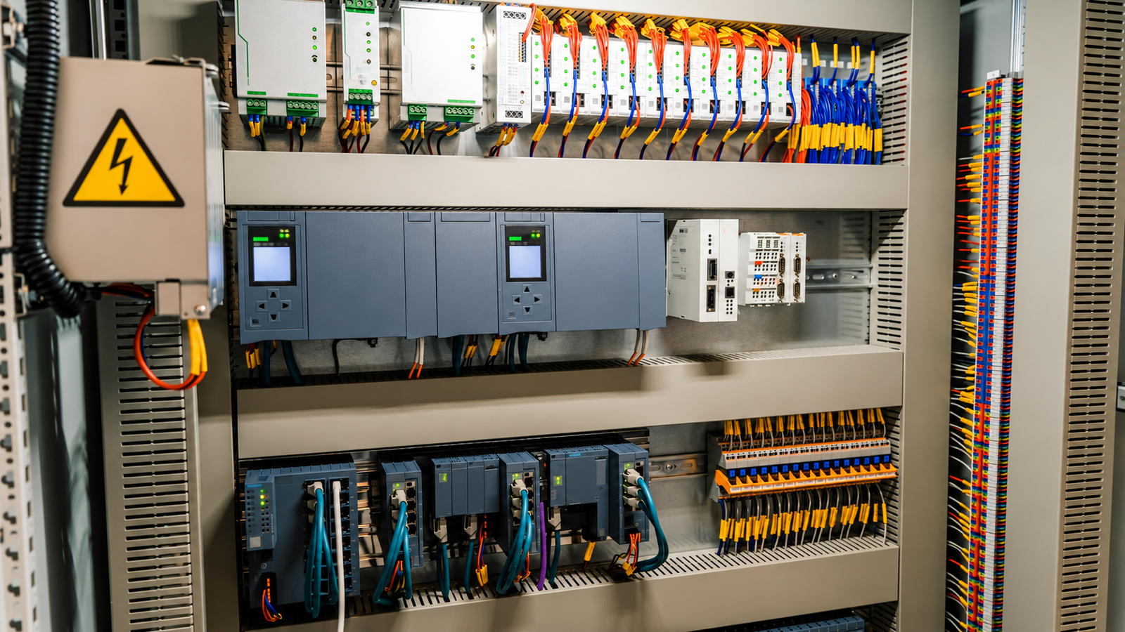
For DIN rail power supplies and control cabinets, the installation can change the EMI result. Long input leads, bundled motor cables, poor earth bonding, and noisy VFD wiring may inject or radiate noise even if the standalone power supply passed a bench test. When an integrator adds an external EMI filter, it should normally sit near the cabinet power entry or near the noisy device, depending on whether the goal is to keep external noise out or keep converter noise inside.
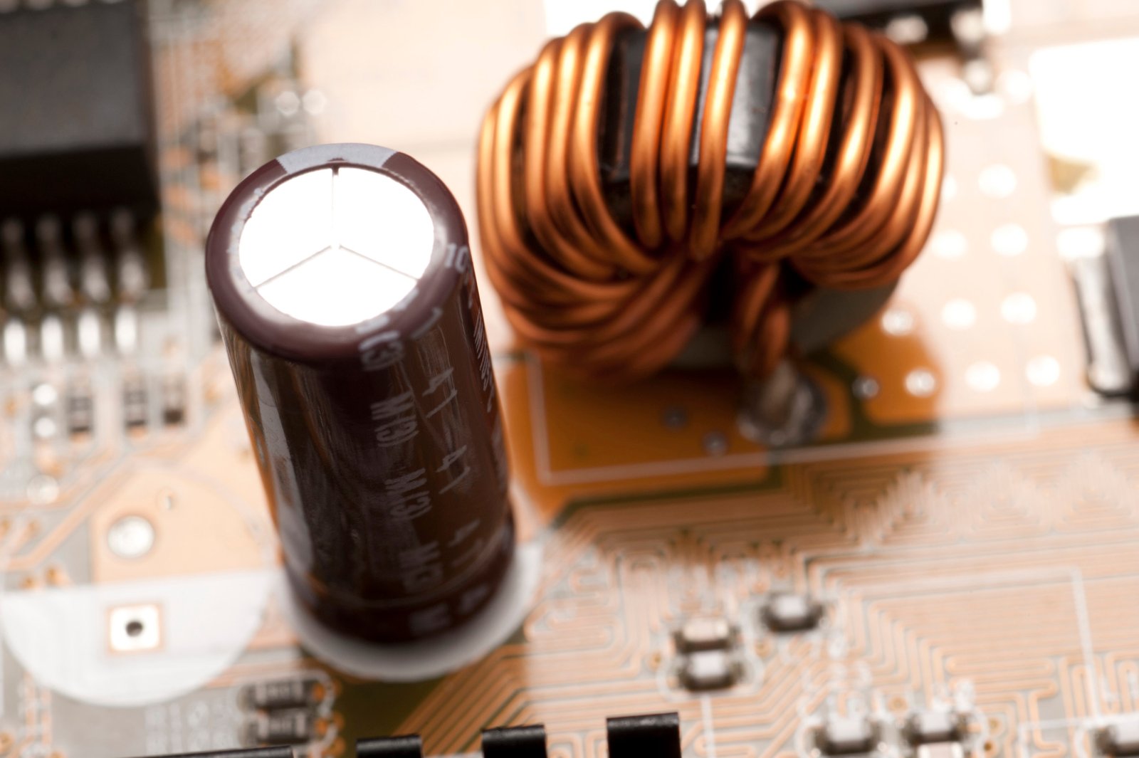
Caption: Filter component placement affects the current loop as much as the nominal component values. Source: ScienceStockPhotos.com, CC BY 4.0 license.
Check rated current, voltage, temperature, and mechanical fit
For procurement teams, a filter datasheet should be read like a power component datasheet, not like a generic accessory sheet. A filter with an attractive attenuation graph may still be unsuitable if the current rating, thermal behavior, voltage rating, or installation method does not fit the equipment.
The rated current must exceed the real operating current, including expected ambient temperature and enclosure conditions. A filter that is rated at 10 A in open air may run hotter inside a sealed cabinet at 50 degrees C. Check whether the current rating is specified at a certain ambient temperature and whether derating is required.
Voltage rating is also more than the nominal mains voltage. For 220 to 240 VAC systems, designers must consider line tolerance, peak voltage, transients, surge testing, and safety-category requirements. A casual rule such as "choose 600 V" is not enough by itself. The selected filter components need ratings and approvals that match the final product's compliance path.
Mechanical fit includes lead style, terminal type, creepage and clearance, vibration, mounting screws, and service access. In compact enclosed power supplies, board-mounted filters save space. In industrial cabinets, chassis-mounted filters with screw terminals can be easier to install and replace. In high-vibration equipment, a heavy choke needs secure mounting so solder joints do not carry mechanical stress.
Avoid creating a new problem while solving EMI
EMI filters interact with the power source and converter. Adding inductance and capacitance can create resonance, increase inrush current, affect hold-up behavior, or make a converter unstable if the source impedance becomes too high.
Input filters on DC-DC converters deserve special attention. A switching converter can look like a negative incremental resistance at its input. If the input filter is poorly damped, it may oscillate with the converter control loop. In practice, damping networks, electrolytic capacitors with suitable ESR, or input-filter design checks may be needed.
On AC inputs, a larger X capacitor or common-mode choke may improve one part of the spectrum and worsen another through resonance. A filter that passes in one enclosure may fail when the cable length changes. This is why pre-compliance testing is so valuable: it shows whether a component change lowered the actual emission peak or only moved it.
Leakage current is another common trap. Increasing Y capacitance is often effective against common-mode noise, but it can push leakage current beyond safety limits. In medical, instrumentation, and user-accessible equipment, this tradeoff must be handled early rather than after the design is mechanically finished.
Use testing to close the selection loop
The best EMI filter selection process is iterative but controlled. Start with the noise type and frequency range, choose a filter structure, check safety and current ratings, then test with the real power supply, load, enclosure, and cable configuration.
For conducted emissions, test with a LISN and an EMI receiver or spectrum analyzer. Record the dominant peaks before and after filter changes. Separate common-mode and differential-mode current when possible so you know whether to adjust the common-mode choke, X capacitor, Y capacitors, differential inductance, or layout.
For radiated emissions, remember that the input filter may only be one part of the solution. High dv/dt nodes, transformer shielding, cable routing, enclosure openings, and grounding can dominate. A common-mode choke on the input may reduce one conducted path while an output cable still radiates.
The final filter should be verified under realistic conditions: minimum and maximum input voltage, full load and light load, expected cable lengths, enclosure closed, normal grounding, and the highest ambient temperature relevant to the application.
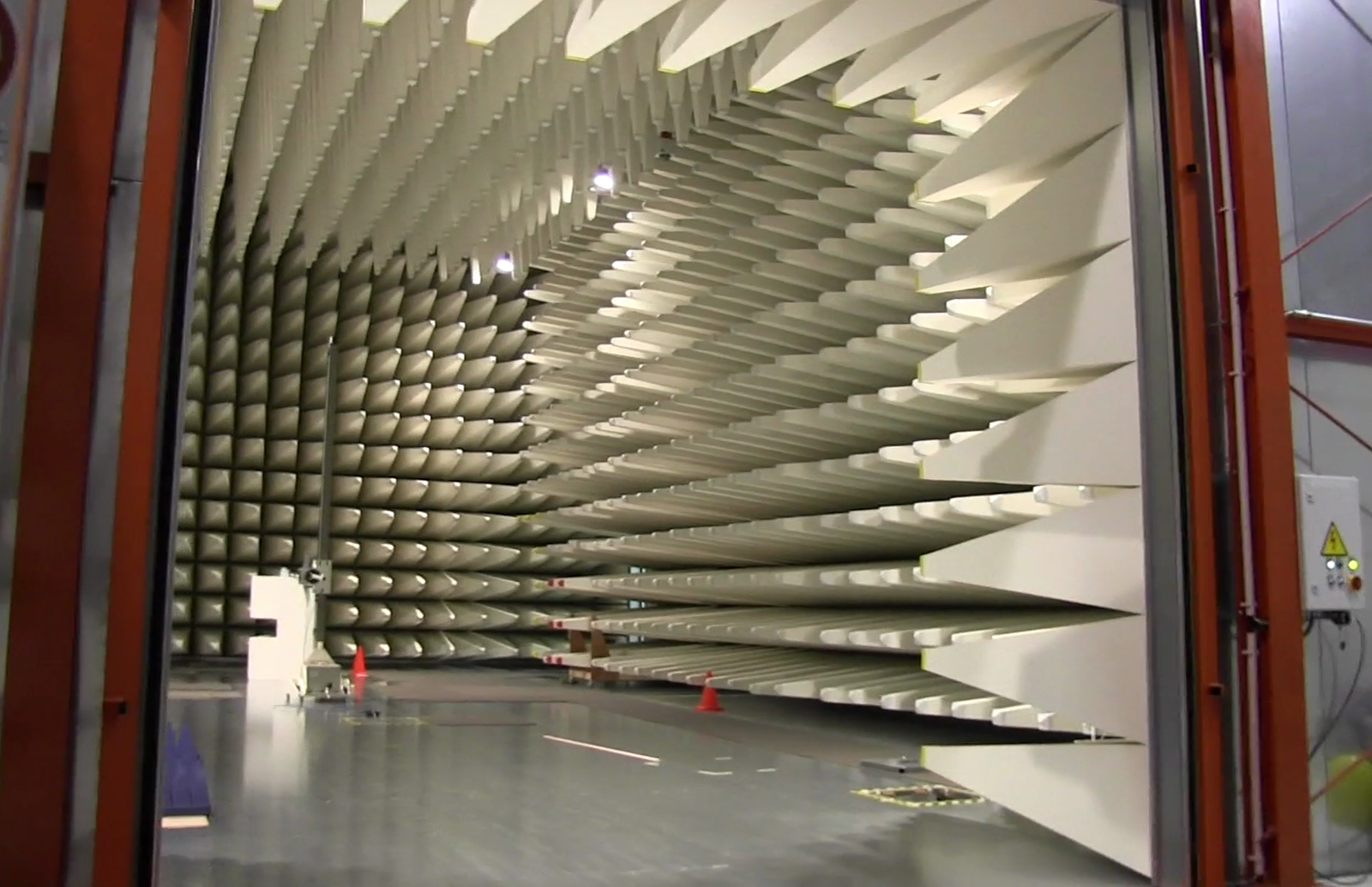
Caption: Formal EMC testing checks the complete equipment system, not only the filter schematic. Source: Wikimedia Commons, author Binarysequence, CC BY-SA 3.0.
Practical selection checklist
Use this checklist before freezing the filter design or approving a power supply for a product platform.
| Selection question | Why it matters | Evidence to request or verify |
|---|---|---|
| Is the dominant noise common-mode, differential-mode, or mixed? | Each noise path needs a different filter element | LISN scan, current-probe check, pre-compliance report |
| Does the filter cover the problem frequency range? | Inductance alone does not predict high-frequency attenuation | Impedance curve, insertion loss data, actual emissions result |
| Are X and Y capacitors correctly safety-rated? | Mains-connected capacitors must fail safely | Safety certificates, part numbers, BOM review |
| Is leakage current acceptable? | Larger Y capacitance can cause safety failure | Leakage-current calculation and test data |
| Is the current rating valid in the real enclosure? | Heat reduces margin and lifetime | Temperature-rise data, derating curve, cabinet ambient |
| Is the layout or installation bypassing the filter? | Noise can couple around the filter through wiring or chassis paths | PCB review, cabinet wiring review, near-field scan |
| Has the filter been tested with real cables and load? | EMI behavior changes with installation | Final pre-compliance or certified EMC report |
Conclusion: choose the filter for the system, not the catalog
Choosing an EMI filter for a switching power supply starts with understanding the noise path. Differential-mode noise needs a different treatment from common-mode noise. X capacitors, Y capacitors, common-mode chokes, and differential inductors all have useful roles, but their ratings, placement, and interaction with the system decide whether they work in practice.
For B2B buyers, the most reliable approach is to evaluate the power supply as part of the equipment environment: input voltage range, load profile, cabinet wiring, grounding, cable length, safety class, leakage-current limit, and target EMC standard. A well-selected filter should reduce emissions without adding overheating, instability, excessive leakage, or installation complexity.
SIPURUI supports industrial switching power supply applications where EMC performance, installation reliability, and practical selection support matter. If your project involves control cabinets, automation equipment, LED systems, or other industrial loads, use EMI filter selection as part of the power supply evaluation process rather than a late-stage fix.
Buyer Checklist
- Identify whether the dominant EMI path is common-mode, differential-mode, or mixed.
- Review choke impedance curves, rated current, saturation behavior, DCR and temperature rise.
- Confirm X and Y capacitor safety approvals, leakage current and insulation requirements.
- Validate filter placement with the real enclosure, grounding, cables and load condition.
- Request LISN, pre-compliance or EMC test evidence before freezing the supply selection.