An AC/DC module and a DC/DC module may deliver the same 24 VDC output, yet they solve different problems. The AC/DC unit must connect safely to the mains, survive line disturbances, control inrush current, meet conducted-emissions limits, and maintain adequate insulation. A DC/DC unit starts with an existing DC source and is normally chosen to change the voltage, stabilize a rail, create an isolated domain, or place regulation close to the load.
Overview
An AC/DC module and a DC/DC module may deliver the same 24 VDC output, yet they solve different problems. The AC/DC unit must connect safely to the mains, survive line disturbances, control inrush current, meet conducted-emissions limits, and maintain adequate insulation. A DC/DC unit starts with an existing DC source and is normally chosen to change the voltage, stabilize a rail, create an isolated domain, or place regulation close to the load.
For an equipment designer or buyer, the practical question is not simply whether the output is DC. It is where the power comes from, what must be isolated, and what the converter has to withstand before that output is usable.
What Is a Power Module?
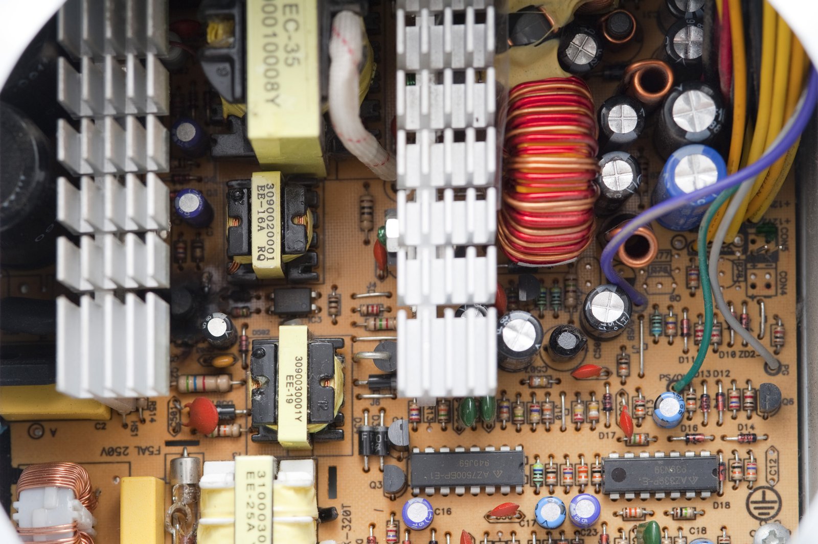
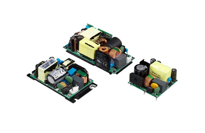
A power module is a compact converter assembly that integrates much of the switching power stage into one component or enclosed subassembly. Depending on the product, it may include the controller, switching devices, transformer or inductor, rectification, feedback, and protection circuits. Some modules are PCB-mount components; others are chassis-mount, encapsulated, open-frame, or DIN-rail units.
“Module” does not mean that every external component has disappeared. An AC/DC PCB module may still require an input fuse, metal-oxide varistor, EMI components, or output capacitors to achieve the conditions stated in its datasheet. A DC/DC module may need input decoupling, a π filter, remote-sense routing, or a recommended footprint. The manufacturer’s test circuit and application notes therefore matter as much as the headline rating.
The benefit is a shorter development path. A well-documented module lets an engineering team start from a characterized power stage instead of designing a converter from individual magnetics and semiconductors. That can reduce layout risk and qualification effort, but it does not remove responsibility for system-level safety, EMC, cooling, and protection.
The Core Difference: The Input Source
An AC/DC power module accepts alternating current and produces a regulated DC output. Compact industrial units commonly cover a universal mains range around 85–264 VAC, although the exact limits vary. Some rectifier-front-end products can also operate from a high-voltage DC input, but that capability must be explicitly documented; it should never be assumed from the AC rating.
A DC/DC power module accepts direct current and produces another DC rail. It may step the voltage down, step it up, invert it, or regulate across a range that crosses the output voltage. Common source rails include 5 V, 12 V, 24 V, and 48 V, as well as battery ranges that move substantially with state of charge.
This input distinction changes the entire front end. An AC/DC converter normally contains rectification and high-voltage energy storage and must address mains transients. A DC/DC converter sees a DC source whose behavior depends on the upstream supply, battery, vehicle bus, or backplane.
| Design question | AC/DC power module | DC/DC power module |
|---|---|---|
| Input source | Utility or generator AC; sometimes documented high-voltage DC | Regulated or variable DC bus, battery, or upstream converter |
| Main task | Convert hazardous mains to a controlled DC rail | Change, regulate, distribute, or isolate an existing DC rail |
| Typical front-end concerns | Fuse coordination, surge, inrush, rectification, EMI, leakage current | Input ripple, undervoltage, reverse polarity, reflected ripple, source impedance |
| Isolation | Usually required between mains and SELV output | Optional; available in isolated and non-isolated versions |
| Common system position | First conversion stage | Secondary stage or point-of-load stage |
| Key compliance focus | End-product safety, creepage/clearance, touch current, mains EMC | Bus transients, isolation if used as a barrier, application-specific EMC |
AC/DC Modules Carry the Mains-Side Burden
The extra functions inside an AC/DC module explain why a watt-for-watt comparison with a DC/DC module can be misleading.
Rectification, bulk energy storage, and hold-up time
AC changes polarity every half-cycle. The converter first rectifies it into a pulsating high-voltage DC bus, then uses switching conversion to produce the required output. Bulk capacitance stores energy between line peaks and may keep the output alive during a brief input interruption. This hold-up requirement affects size, inrush current, capacitor life, and cost.
Surge and inrush behavior
The input may see switching events, lightning-related surges, or disturbances from nearby industrial loads. At startup, the discharged bulk capacitor can also draw a short but substantial inrush current. A buyer should check cold-start inrush, permitted cycling rate, recommended fuse type, surge test level, and any external protection network—not only the steady-state input current.
Mains safety and insulation
Clearance, creepage, dielectric strength, insulation class, pollution degree, and overvoltage category influence whether a module fits the end equipment. A printed withstand-voltage number alone does not prove that a product provides the required basic, supplementary, or reinforced insulation. Relevant agency approvals and the conditions in the certificate are more useful.
Leakage or touch current also deserves attention, especially in medical equipment and systems with many paralleled supplies. Input-to-output capacitance that helps control EMI can increase common-mode current.
EMI and power factor
An AC/DC module can meet an emissions limit only under defined test conditions. Enclosure bonding, cable length, earth connection, external filtering, and PCB layout can change the result. Higher-power equipment may also need power-factor correction to satisfy harmonic-current requirements or a customer specification.
DC/DC Modules Offer More Architectural Choices
DC/DC modules range from tiny non-isolated point-of-load regulators to high-isolation converters for medical, railway, energy-storage, and industrial control systems.
Non-isolated DC/DC conversion
When the input and output may share a ground, a non-isolated buck, boost, or buck-boost module is usually compact and efficient. Typical uses include converting a 24 V control rail to 5 V for logic, stepping a battery rail to 12 V, or generating a processor core voltage close to the load.
Grounding is the decisive limitation: a non-isolated module cannot break a ground loop or establish a safety barrier. Its input may also pass faults or common-mode noise into downstream circuitry unless the surrounding design provides suitable protection.
Isolated DC/DC conversion
An isolated DC/DC module transfers energy across a transformer or other galvanic barrier. Designers use it to separate ground domains, power high-side gate drivers, isolate communication interfaces, reduce ground-loop problems, or add a local barrier near sensitive circuitry.
Isolation ratings need context. Working voltage, transient rating, creepage, clearance, insulation system, and safety certification determine how the barrier can be used. A module advertised with a high one-minute test voltage may still be unsuitable as reinforced insulation in the intended end product.
Input range is an engineering requirement, not a nominal label
A “24 V input” does not necessarily mean a module can operate across every 24 V industrial bus condition. The real source may fall during cranking, rise during charging, overshoot when a relay opens, or carry ripple from an upstream rectifier. Define the minimum continuous input, maximum continuous input, transient envelope, and expected source impedance before selecting the converter.
Can an AC/DC Module Accept DC Input?
Some AC/DC supplies specify both an AC input range and a high-voltage DC input range. A bridge rectifier makes this technically possible in many designs, but operation from DC changes several system details:
The approved input range and terminal polarity must come from the datasheet.
A fuse or disconnect device designed for AC may not have an adequate DC interrupt rating.
Input switches, connectors, relays, and surge devices need appropriate DC ratings.
EMC, inrush, protective-earth behavior, and safety certification may differ from the AC test configuration.
Therefore, an AC/DC module with documented DC-input capability does not become a general-purpose low-voltage DC/DC converter. A unit specified for 120–370 VDC input, for example, is not a substitute for a 24 V-input module.
Efficiency and Thermal Design
Efficiency figures are meaningful only when tied to input voltage, output voltage, load, and temperature. An attractive peak value can hide weak performance at the application’s normal load.
For a 40 W output at 90% efficiency, the converter dissipates about 4.4 W:
Loss = Output power ÷ Efficiency − Output power
Loss = 40 W ÷ 0.90 − 40 W ≈ 4.4 W
That heat must leave through the case, PCB copper, airflow, or heatsink. An encapsulated module may tolerate a high ambient temperature at partial load yet require derating at full load. Likewise, a DC/DC brick that is efficient in a vendor test fixture may run hotter when the host board restricts airflow or provides insufficient copper area.
When comparing candidates, ask for efficiency curves rather than a single maximum, then calculate losses at low line, nominal line, and the highest expected load. Check no-load consumption for equipment that spends long periods in standby.
Application Examples
| Application | Likely conversion path | Why |
|---|---|---|
| PLC or industrial controller powered from mains | AC/DC to 24 V, then DC/DC to 5 V and 3.3 V | The first stage handles mains safety; local converters improve rail regulation and distribution |
| Battery-powered instrument | DC/DC only | No mains conversion is required; the converter follows the battery discharge range |
| 48 V telecom or network equipment | 48 V DC/DC intermediate bus and point-of-load stages | Wide-input DC/DC modules support bus variation and local rails |
| Isolated RS-485 or CAN interface | Small isolated DC/DC plus digital isolation | Provides a separate power domain at the interface |
| Medical device connected to AC | Medical-approved AC/DC, sometimes followed by medical isolated DC/DC | The second barrier may be needed near patient-connected circuitry |
| Energy-storage control system | AC/DC auxiliary supply and isolated or bidirectional DC/DC stages | Different stages serve housekeeping, sensing, gate drive, and energy transfer |
These examples also show why “AC/DC or DC/DC?” is often the wrong system-level question. Complex equipment commonly needs both.
How to Choose the Right Module
1. Define the source accurately
Record the continuous input range, frequency if AC, brownout behavior, surge and transient environment, source impedance, polarity risks, and whether regenerative energy can return to the input. Do not use the nominal voltage as the full specification.
2. Build a realistic load profile
Include startup current, capacitive loads, motors, relays, radio bursts, processor transients, and simultaneous channel loading. Decide whether the output needs sequencing, remote on/off, trim, remote sense, or current sharing.
3. Decide what isolation must accomplish
Isolation may be required for user safety, functional noise control, breaking a ground loop, high-side operation, or compliance with an application standard. State the required working voltage and insulation category rather than asking only for “3 kV isolation.”
4. Check thermal performance in the real enclosure
Evaluate worst-case ambient temperature, altitude, airflow, mounting orientation, neighboring heat sources, and PCB copper. Confirm derating at low input as well as high temperature. A prototype temperature test should measure the points specified by the manufacturer.
5. Review protection and fault behavior
Short-circuit, overload, overvoltage, undervoltage, overtemperature, and reverse-polarity responses vary. Hiccup protection may be ideal for one load and prevent another from starting. Confirm whether faults latch, auto-recover, or require input recycling.
6. Treat compliance as a system task
Match the module’s approvals to the end product and target markets. Review the certificate, report conditions, external components, and PCB spacing requirements. Plan pre-compliance EMC and surge testing with production-intent cables and enclosure hardware.
7. Evaluate supplier evidence
For B2B procurement, request full datasheets, safety certificates, EMC test conditions, reliability methodology, change-notification policy, traceability, warranty terms, and lifecycle status. Samples should be tested across input, load, and temperature corners—not only at room temperature and nominal input.
Buyer Checklist
| Item to confirm | Questions for the supplier |
|---|---|
| Electrical rating | What are the minimum and maximum continuous inputs? Is the output continuously rated across that range? |
| Isolation | What are the working voltage, insulation type, creepage, clearance, and applicable certifications? |
| EMC and immunity | Which external filters and layouts were used? What surge, EFT, ESD, and conducted/radiated tests were passed? |
| Thermal limits | What are the case-temperature limit and derating curves? What airflow or PCB copper is assumed? |
| Protection | How does the module respond to overload, short circuit, overvoltage, reverse input, and overtemperature? |
| Lifetime | Which components limit service life? At what temperature and load was lifetime estimated? |
| Manufacturing | Are lot traceability, PCN control, and long-term supply support available? |
Common Selection Mistakes
The first is comparing only output voltage and wattage. Two 24 V, 30 W modules may have very different isolation, transient, temperature, and EMC capabilities.
The second is confusing dielectric test voltage with usable isolation. A safety barrier is defined by more than a single hipot number.
The third is overlooking the module’s external circuit. If compliance depends on a specific fuse, filter, capacitor, or spacing pattern, that part of the reference design must be carried into the product.
The fourth is assuming that the maximum advertised temperature permits full load. Derating curves and case-temperature measurements decide usable power.
Finally, do not select solely from a low unit price. A cheaper module can increase total cost if it requires additional filtering, heatsinking, requalification, or field service.
Conclusion
An AC/DC module is the bridge from mains power to a safe, regulated DC bus. A DC/DC module reshapes an existing DC rail and may add local regulation or galvanic isolation. The correct choice follows from the source, the required barrier, the real load profile, and the electrical and environmental conditions—not from output voltage alone.
For industrial equipment, the most robust architecture often combines a qualified AC/DC front end with one or more DC/DC stages near sensitive loads. SIPURUI can support module selection around input range, output power, isolation, mounting, thermal constraints, and target application. Sharing the power-tree diagram and worst-case operating conditions early is the fastest route to a meaningful recommendation.