A DC-DC converter rarely fails because its nominal input voltage was misunderstood. More often, damage happens at the edges of the operating envelope.
A DC-DC converter rarely fails because its nominal input voltage was misunderstood. More often, the damage happens at the edges of the operating envelope: a connector is reversed during service, a long cable rings during hot plug, a 24 V bus rises above its usual tolerance, or an input capacitor pulls far more current than the upstream source can deliver.
The protection network has to keep those events away from the converter and the load without creating a new problem in normal operation. A series diode may stop reverse polarity but waste too much voltage in a low-voltage, high-current system. A TVS diode may clamp a fast transient yet overheat during a sustained overvoltage. A fuse can isolate a hard fault, but it is usually too slow to protect a semiconductor junction by itself.
The useful design question is therefore not, "Which protection parts should we add?" It is, "What fault must the system survive, for how long, and in what state should it recover?"
Start with a fault envelope
Before selecting components, write down the electrical events that can reach the input connector. Include steady-state limits, transient polarity, source impedance, pulse duration, repetition rate, cable inductance, maximum load current, and the amount of input capacitance behind the protection stage. Then decide the required outcome for each event: continue operating, ride through briefly, shut down and retry, latch off, or sacrifice a replaceable fuse.
That distinction matters. A machine controller may need to ride through a short disturbance without losing state. A battery-powered product may prefer immediate disconnection to protect energy reserves. In an unattended installation, an automatically resetting protection controller can be more useful than a crowbar that requires a fuse replacement.
| Fault | Electrical question to define | Acceptable system response | Main design constraint |
|---|---|---|---|
| Reverse connection | Maximum negative voltage and duration | Block input and reverse current | MOSFET voltage rating, gate stress, body-diode orientation |
| Fast surge | Waveform, source impedance, peak, repetition | Clamp or divert energy | TVS clamping voltage, pulse power, layout inductance |
| Sustained overvoltage | Maximum voltage and duration | Disconnect or regulate through | Pass-FET SOA, timer, thermal rise |
| Inrush current | Input capacitance, cable/source impedance | Controlled capacitor charge | Peak current, startup time, hot-plug ringing |
| Brownout | Minimum input and recovery profile | Clean shutdown or ride-through | UVLO thresholds, hysteresis, hold-up energy |
| Output overload | Current level and fault duration | Limit, hiccup, or latch off | Switch current, inductor saturation, connector and trace heating |
Reverse polarity is not the same as reverse current
A series Schottky diode is still a reasonable answer for a small current rail. It is simple, predictable, and blocks current in both directions when reverse-biased. Its penalty is conduction loss. At 5 A and a 0.45 V forward drop, the diode dissipates about 2.25 W and removes 0.45 V from the converter's input budget.
A high-side P-channel MOSFET reduces that loss and can be self-biased with few components. Check more than the headline RDS(on), though. The gate-source voltage must remain within its absolute maximum rating during positive and negative input events, and the device must be sufficiently enhanced at the lowest valid input voltage. Cold temperature and a weak gate drive can turn an apparently low-loss solution into a reset problem.
For higher current, an N-channel MOSFET with a reverse-polarity or ideal-diode controller usually gives lower resistance for the same silicon area. Texas Instruments makes an important distinction: a reverse-polarity controller blocks a reversed supply, while an ideal-diode controller also responds quickly to reverse current from the load back toward the source. That second behavior matters when large hold-up capacitors or another supply can energize the downstream rail.
Back-to-back MOSFETs are appropriate when the design must block current in both directions after shutdown. A single MOSFET cannot always provide that isolation because its body diode leaves one current path available.
| Approach | Normal-operation loss | What it blocks | Best fit | Watch-outs |
|---|---|---|---|---|
| Series Schottky diode | VF x I | Reverse polarity and reverse current | Low current, low BOM count | Voltage headroom and heat |
| P-channel MOSFET | I² x RDS(on) | Reverse polarity; reverse-current behavior depends on circuit | Moderate current, simple high-side design | Gate clamp, low-input drive, device resistance |
| N-channel MOSFET plus controller | Low I²R loss plus controller current | Reverse polarity; ideal-diode types can block reverse current | Higher current or tight voltage budget | Controller range, gate drive, response time |
| Back-to-back MOSFETs | Two FET resistances in series | Bidirectional off-state isolation | Shared rails, charged loads, robust disconnect | Cost, area, control sequencing |

Overvoltage protection needs a time axis
"Overvoltage" can mean a 100 ns spike, a millisecond surge, or a supply stuck above its intended setpoint for seconds. Those are different thermal problems.
A TVS diode is effective for fast, bounded transients when it is selected from the full set of voltage parameters. The reverse standoff voltage must sit above the highest legitimate bus voltage, including tolerance. The maximum clamping voltage at the relevant peak pulse current must remain below the protected circuit's withstand limit. The peak pulse rating must be checked against the specified waveform and temperature, not treated as a continuous-power rating.
Placement also matters. The current loop from the connector through the suppressor and back to the return should be short and wide. Trace inductance adds voltage during a fast di/dt event, so a suitable TVS placed far from the connector may deliver a much worse clamp at the converter pins than its data sheet suggests.
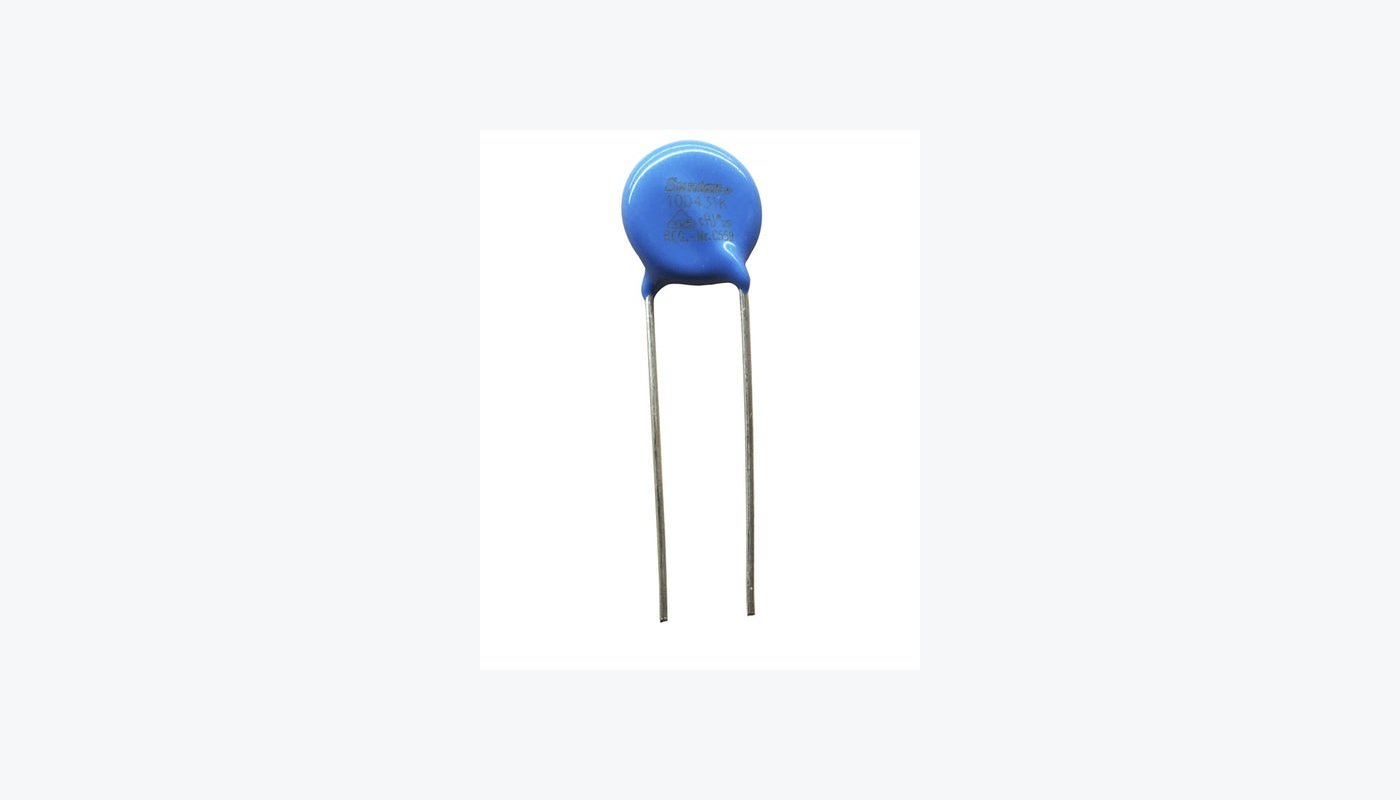
MOVs are common where higher-energy events and higher bus voltages justify them. Their leakage, voltage tolerance, aging, and end-of-life behavior must be included in the design. A MOV or TVS also needs upstream impedance or a coordinated disconnect device; no clamp can absorb unlimited energy from a stiff source.
When the event lasts too long for a shunt suppressor, a series protection stage is usually the better tool. An overvoltage protection controller can disconnect the load. A linear surge stopper can regulate the protected output by operating a pass MOSFET in its linear region, provided the MOSFET stays inside its safe operating area. Switching surge stoppers reduce dissipation in higher-power ride-through applications but add magnetic components, switching behavior, and control complexity.
The system decision is straightforward: disconnect if interruption is acceptable; design for ride-through only when continuous operation is worth the extra thermal and electrical burden.
Coordinate the fuse, clamp, and disconnect stage
A fuse is an isolation device, not a precision semiconductor protector. Its opening time depends on fault current, ambient temperature, mounting, and the time-current curve. A fuse rated at the normal load current may carry a modest overload far longer than the MOSFET or TVS can tolerate.
Crowbar protection uses an SCR or similar device to force a large current after an overvoltage threshold is crossed, causing the fuse to open. It can be effective when the upstream source has enough fault current and the product can tolerate a latched shutdown. It is a poor fit if the source is current-limited, the wiring cannot withstand the prospective fault, or field replacement is difficult.
A layered front end often works better: the fuse protects wiring against sustained high current, the TVS handles a defined fast pulse, and the electronic disconnect responds to abnormal voltage or current that lasts longer. Each device then has a specific job and an energy limit that can be tested.
Inrush control is about capacitor charging
At connection, an uncharged input capacitor initially looks close to a short circuit. A rough first estimate is I = C x dV/dt. Charging 2,000 uF from 0 V to 24 V in 1 ms implies an average capacitor current of 48 A before cable resistance, ESR, switching behavior, and ringing are considered.
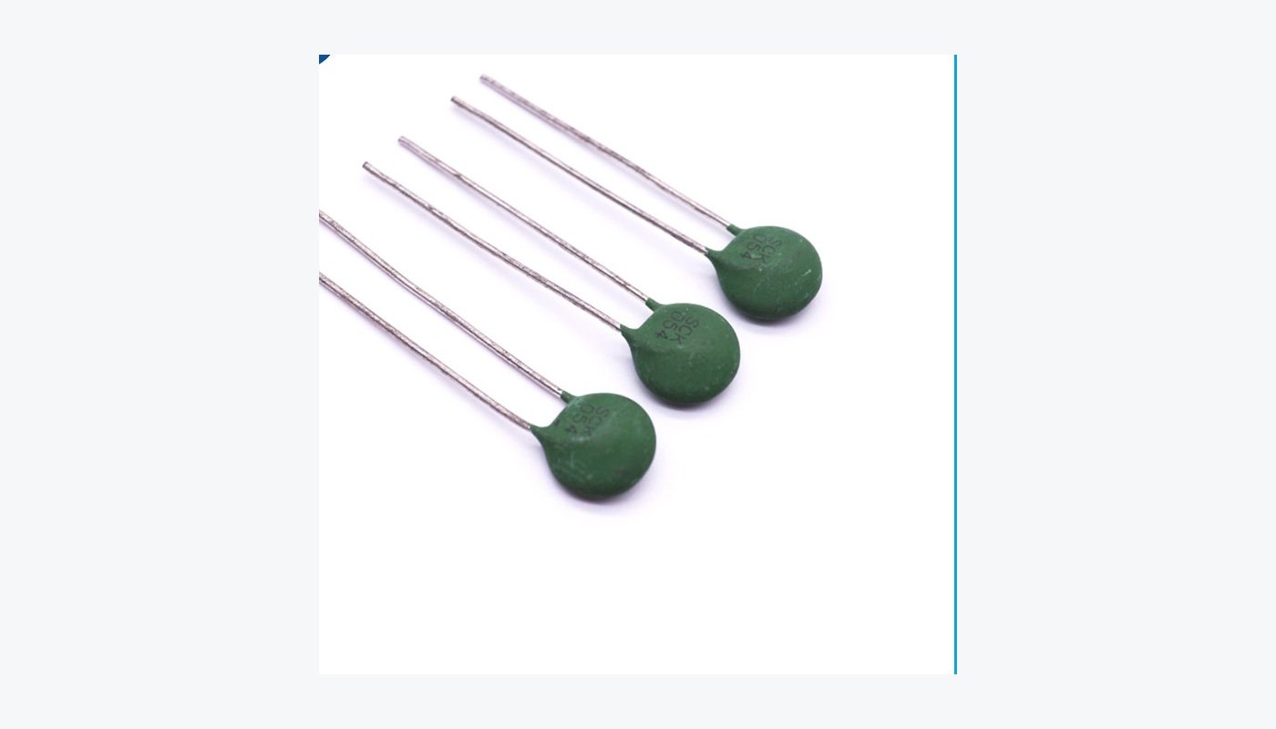
An NTC thermistor is inexpensive and often adequate for equipment that starts infrequently. It begins with a relatively high resistance and drops as it warms. That behavior becomes a liability during a quick off-on cycle: a hot NTC may provide little limiting just when the next inrush event arrives. It also dissipates power in steady operation unless a relay or MOSFET bypasses it.
For frequent hot plug, wide ambient temperature, or controlled startup timing, an active hot-swap or eFuse solution is easier to specify. It can ramp the pass MOSFET gate, monitor current, enforce a fault timer, and report power-good status. The MOSFET still requires an SOA calculation during capacitor charging and fault current limiting.
UVLO must include hysteresis and source behavior
Undervoltage lockout keeps a converter from trying to operate where it cannot regulate reliably. The turn-off threshold should be high enough to avoid excessive input current, control instability, or repeated current-limit operation. The turn-on threshold must also leave enough margin for source droop when the load is applied.
Hysteresis prevents chatter. Without it, the converter may start, pull the weak source below the UVLO threshold, shut down, allow the source to recover, and then repeat the cycle. That pattern can stress the input switch and create intermittent resets that are hard to reproduce in the lab.
For battery systems, UVLO also protects the source from over-discharge. For long-cable industrial systems, it may need to tolerate brief voltage dips while rejecting a genuinely collapsed supply. Hold-up capacitance, a backup source, or a UPS belongs in the system architecture when the load must continue running through an interruption. Board-level UVLO cannot create missing energy.
Output overload behavior must match the load
Current limiting can be constant-current, foldback, hiccup, or latch-off. Constant-current limiting may help a capacitive load start, but it leaves the converter dissipating power during a hard short. Foldback reduces fault power but may prevent a load with high startup current from recovering. Hiccup periodically retries and lowers average heating. Latch-off provides a clear safe state but requires a reset mechanism.
Check the complete path, not just the controller's current limit. The inductor must avoid saturation at peak current. MOSFETs, rectifiers, shunts, connectors, copper, and output wiring all need compatible short-circuit withstand. If the load contains motors, solenoids, or large capacitors, its startup and regenerative behavior should be part of the test plan.
Protection testing should reproduce the real fault
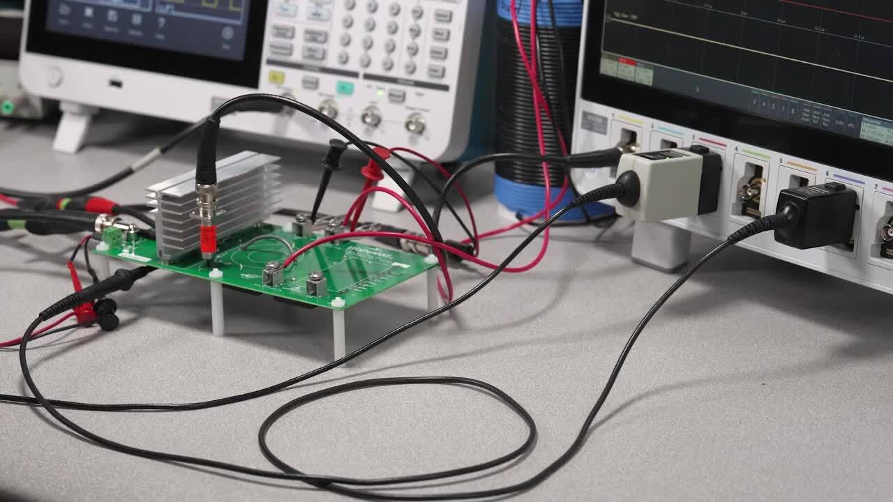
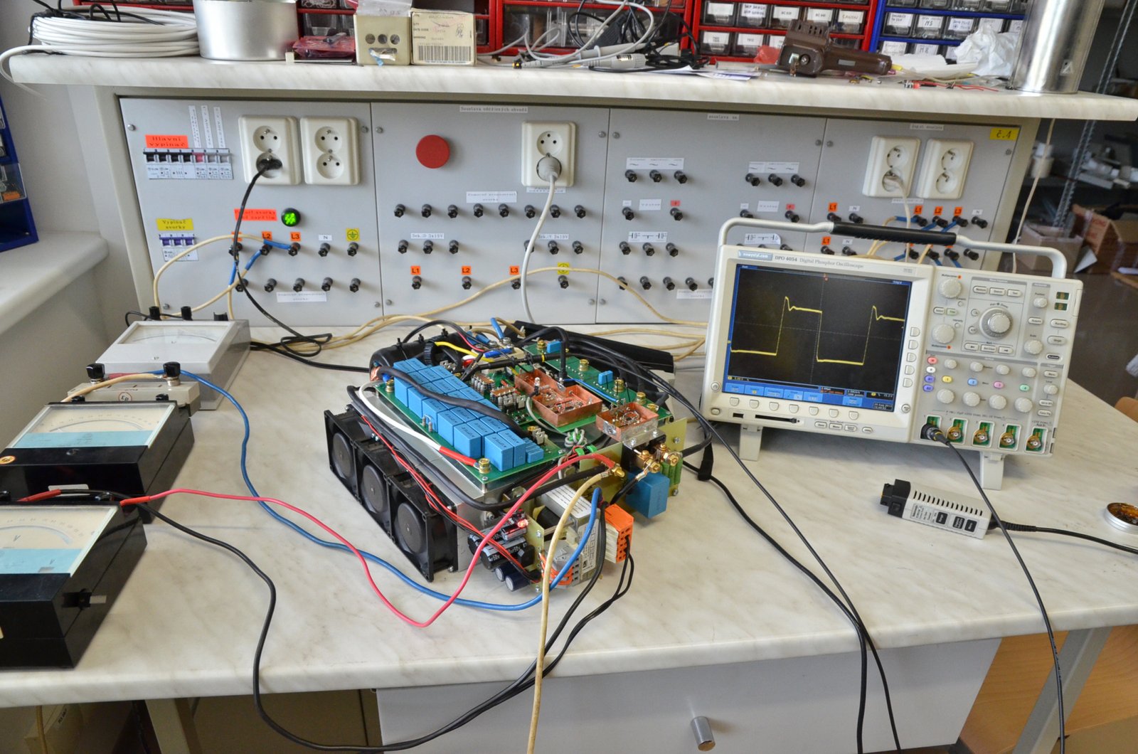
Bench testing should cover component tolerances and operating corners rather than one nominal demonstration. Record the input waveform at the connector and at the converter pins, along with pass-FET current, gate voltage, and the protected output. Use a differential probe or an appropriately isolated measurement method where ground references are not common.
The validation matrix should include minimum and maximum input, maximum load, no load, hot and cold starts, rapid power cycling, reversed input, short circuit, transient pulses, and recovery after every fault. For a pass MOSFET, compare the measured voltage-current-time trajectory with the data-sheet SOA curve at the worst expected junction temperature.
Standards supply test methods and environmental context, but they do not replace the product's own fault envelope. IEC 61000-4-5 addresses surge immunity test methods. IEC 61131-2 covers functional and EMC requirements for industrial control equipment. ISO 16750-2:2023 covers electrical loads for road-vehicle electronics, including supply discontinuities and reversed voltage. Apply only the standards relevant to the end product, installation category, and market.
A practical selection checklist
| Design decision | Evidence to collect before schematic release |
|---|---|
| Reverse connection | Negative-voltage limit, duration, reverse-current requirement, connector and fuse behavior |
| TVS or MOV | Bus maximum, waveform, source impedance, clamp at actual current, pulse repetition, temperature derating |
| Series protection | Normal loss, maximum fault voltage, MOSFET SOA, disconnect time, retry or latch policy |
| Inrush limiting | Total downstream capacitance, desired rise time, source current limit, rapid-restart case |
| UVLO | Source droop, converter minimum input, turn-on and turn-off thresholds, hysteresis, hold-up requirement |
| Overcurrent response | Load startup profile, short-circuit current, thermal limit, recovery behavior |
| Compliance | Applicable product standard, test level, coupling method, pass criteria, test report ownership |
Build a protection chain, not a parts pile
A robust DC-DC input stage usually has several layers, but every layer should trace back to a fault definition. Reverse-polarity circuitry controls current direction. A suppressor deals with a bounded transient. A fuse or electronic switch isolates sustained faults. Inrush control manages stored energy, while UVLO and output current limiting keep the converter inside a stable operating region.
For an industrial power supply project, ask the supplier for more than a feature list. Request the threshold tolerances, protection timing, recovery behavior, derating conditions, and the test standards behind each claim. SIPURUI can support converter and switching power supply selection around the actual input bus, load profile, installation environment, and required fault response.