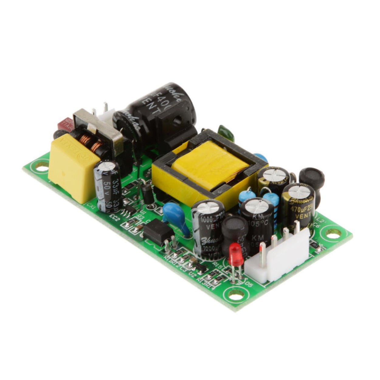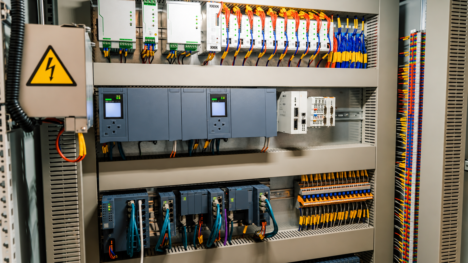
A 24 V power supply can look suitable on a quotation and still struggle inside a warm control cabinet. Its continuous output rating may fall with temperature, a valve bank may pull the voltage down during switching, or an auxiliary rail may drift when the main load goes idle. Understanding the converter topology helps engineers ask better questions before those problems reach the machine.
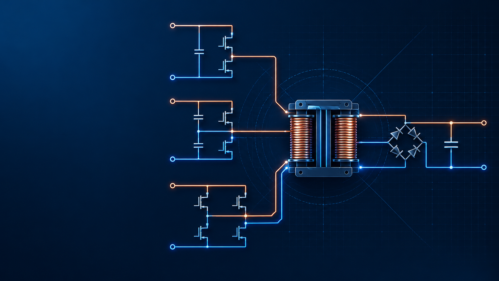
In a forward vs flyback converter comparison, the central difference is when energy reaches the output. A flyback stores magnetic energy during the primary switch on-time and delivers it through the secondary during the off-time. A forward converter transfers power through the transformer during the on-time; its output inductor supports the load between transfer intervals.
Flyback is often a practical starting point for a compact, economical isolated supply. Forward deserves consideration when sustained output current and output filtering justify its extra components. Neither name guarantees efficiency, reliability, or regulation. Those depend on the complete design and its operating conditions.
How a flyback converter works
The flyback magnetic component behaves as a coupled inductor. Engineers commonly call it a transformer because it also provides isolation and a turns ratio, but energy storage is central to its operation.
When the primary MOSFET turns on, current rises in the primary winding. The winding polarity and rectifier orientation keep the secondary rectifier off. During this interval, the output capacitor supplies the load.
When the MOSFET turns off, the winding voltage reverses. The secondary rectifier conducts, and stored magnetic energy reaches the output. Secondary current supplies the load and replenishes the capacitor. The two windings therefore carry their main power-transfer currents during different intervals of the switching cycle.
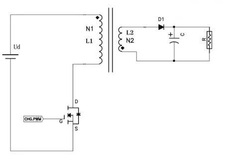
In discontinuous conduction mode, or DCM, the magnetizing current falls to zero before the next cycle. In continuous conduction mode, or CCM, some magnetizing current remains. Boundary operation sits between the two. A flyback can use any of these modes; its topology does not force DCM.
The choice changes more than the current waveform. DCM tends to produce higher peak current for the same average power, which increases conduction loss and current stress but can simplify the small-signal behavior of the power stage. CCM reduces peak-to-average current and may suit higher power, yet its control loop must account for a right-half-plane zero in many operating conditions. Boundary mode varies the switching frequency so each cycle begins close to zero current. It can reduce turn-on loss, but the variable frequency must be considered during EMI testing and magnetic design.
The usual gapped ferrite construction accommodates the required energy storage, with much of that energy stored in the gap. The gap is part of a coordinated magnetic design involving turns, current, core area, and allowable flux excursion. Adding a gap alone does not make an overloaded transformer safe from saturation.
The transformer specification should state magnetizing inductance, leakage inductance, turns ratio, insulation system, winding resistance, and saturation current at the relevant temperature. A value measured at room temperature and low signal level may not describe the component under peak operating current. Core loss, copper loss, fringing near the gap, and winding temperature must be checked across the complete input and load range. Winding arrangement also involves a tradeoff: tighter coupling can reduce leakage, while insulation spacing and lower interwinding capacitance may require more physical separation.
How a forward converter works
A forward converter uses its transformer primarily to transfer power while the primary switch is on. The secondary rectifier conducts in that same interval, supplying the output through an inductor. When the switch turns off, the output inductor current continues through a freewheeling path. In a conventional diode implementation, a second diode provides that path.
This is why a forward converter is often described as an isolated buck-derived topology. The output inductor is part of the energy-conversion stage. Removing it changes the circuit behavior; it is not simply an optional noise filter.
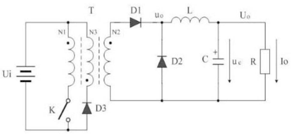
The transformer still has finite magnetizing inductance and stores some magnetizing energy. Its reset circuit applies reverse volt-seconds so that flux does not accumulate from cycle to cycle. That magnetizing energy is distinct from the main load energy transferred while the switch conducts.
A reset winding is one solution. Other arrangements include a two-switch forward circuit and active-clamp or resonant-reset designs. The familiar 50% duty-cycle limit applies to particular reset arrangements, such as an equal-turn reset winding, rather than every forward converter.
The reset method affects usable duty ratio, switch voltage, loss, and transformer construction. A passive RCD reset network is simple but dissipates energy. A two-switch forward arrangement returns magnetizing energy to the input and limits the ideal voltage across each main switch to approximately the input bus. An active clamp adds a controlled switch and can recycle energy while enabling a wider duty-cycle range. These alternatives should be compared as complete circuits because a lower transformer count or lower switch rating in one area can be offset by gate-drive complexity elsewhere.

The differences that affect a real design
The comparison below describes conventional implementations. Synchronous rectification, active clamps, and additional filters can change the component count and loss balance.
| Design point | Flyback converter | Forward converter |
|---|---|---|
| Main transfer interval | Primary switch off-time | Primary switch on-time |
| Main magnetic storage | Coupled inductor magnetizing inductance | Separate output inductor |
| Output current delivery | Secondary delivers pulses to the output | Output inductor smooths current; it can remain continuous in CCM |
| Transformer reset | Secondary conduction provides reverse volt-seconds | A suitable reset arrangement is required |
| Basic secondary stage | Rectifier and capacitor | Rectifier, freewheeling path, inductor, and capacitor |
| Additional output rails | Often economical to add; cross-regulation needs attention | Possible, with suitable filtering and regulation for each rail |
| Typical design attraction | Low component count and flexible isolated outputs | Sustained current delivery and lower capacitor ripple-current burden |
Winding dots indicate instantaneous voltage polarity. They help explain which rectifier conducts, but a dot drawn at the top or bottom of a page is not enough to identify a topology. Follow the switching state, rectifier orientation, and current path.
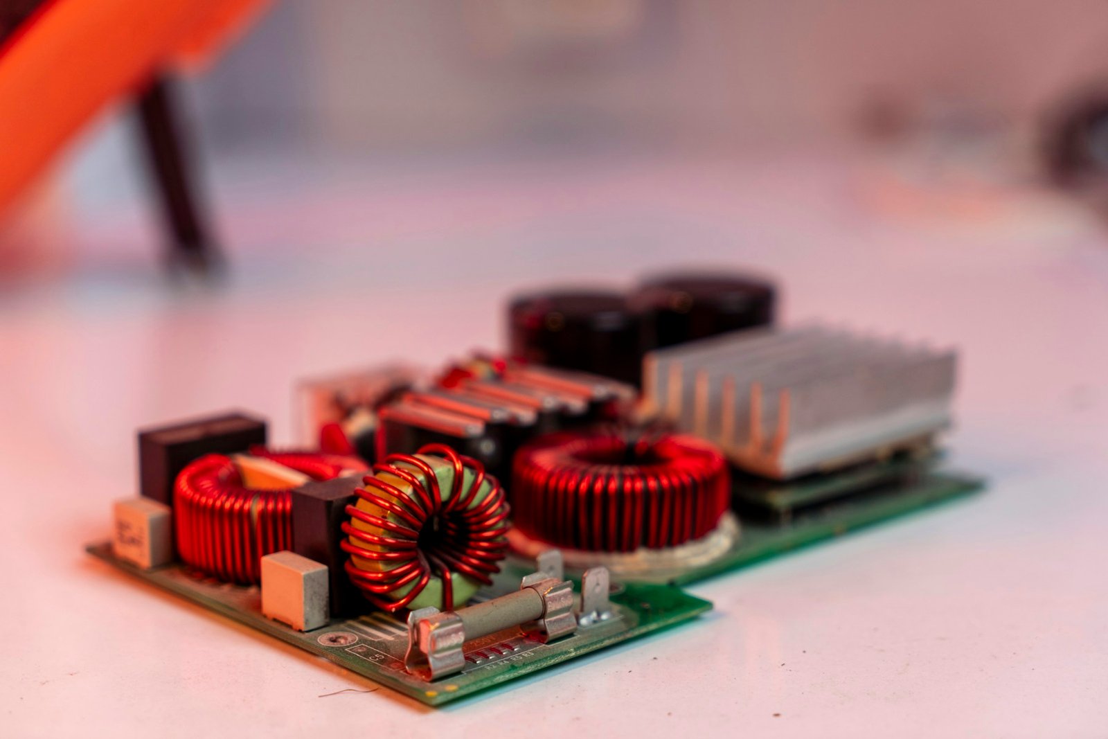
Likewise, seeing an inductor near the output does not prove that a board is forward. A flyback may include a downstream LC filter. The useful distinction is whether the inductor forms the forward power stage's main energy-storage and freewheeling path.
Power rating is a starting point rather than a cutoff
The rule “flyback below 100 W, forward above 100 W” is too rigid for procurement or design reviews. It describes a familiar historical preference, but it does not account for input range, output current, cooling, switching devices, or converter variants.
Interleaved and active-clamp flyback designs can operate beyond the range associated with a basic single-switch flyback. That does not mean every flyback scales efficiently to several hundred watts. The additional switches, magnetics, control, and thermal work make it a different implementation rather than a free extension of the simple circuit.
Interleaving divides the input and output ripple between phases and spreads heat across more components. It also requires phase-current balance and adds controller, sensing, and magnetic cost. An active-clamp flyback can recover leakage energy and support softer switching, but clamp timing and circulating current must be tuned over line and load. At some point, a forward, half-bridge, or LLC implementation may reach the same power with lower RMS current. The appropriate crossover point depends on the product, not a universal wattage number.
As power rises, examine peak and RMS current, winding losses, rectifier losses, capacitor heating, and the clamp circuit. These costs can outweigh the apparent saving from a smaller bill of materials. Forward adds an output inductor and a freewheeling path, but the resulting current waveform can be useful for a sustained high-current output.
The following cases are selection examples, not prescribed topology limits or SIPURUI product specifications.
| Example requirement | Reasonable starting point | What should decide the choice |
|---|---|---|
| 24 V at 1 A for sensors and a controller | Evaluate a flyback first | Standby loss, enclosure temperature, isolation, and total cost |
| 24 V at 5 A for mixed control loads | Compare qualified flyback and forward implementations | Thermal derating, load steps, ripple, and available space |
| 24 V at 10 A with sustained loading | Include forward in the shortlist; compare other suitable topologies | Continuous current losses, cooling, and efficiency across the operating range |
| Several low-power isolated bias rails | A multi-output flyback may be economical | Voltage error when each rail is independently loaded |
For a finished power supply, ask for the guaranteed operating envelope before requesting a particular circuit. A topology preference should not exclude a design that has better measured performance in the actual equipment.
What the flyback equations explain
For an ideal fixed-frequency DCM flyback, starting each cycle from zero magnetizing current, the stored energy per cycle is:
E = 0.5 × Lm × Ipk²
The corresponding ideal transferred power is:
Pideal = 0.5 × Lm × Ipk² × fs
During the on-time:
Ipk = Vin × D / (Lm × fs)
Combining these expressions gives:
Lm = Vin² × D² / (2 × Pideal × fs)
Here, Lm is primary-referred magnetizing inductance, Ipk is peak magnetizing current, fs is switching frequency, D is duty ratio, and Vin is the DC voltage actually applied to the primary stage. Pideal is an ideal energy-transfer quantity. For an initial practical estimate, output power is approximately efficiency multiplied by Pideal; losses must then be evaluated separately.
At fixed Vin, D, and fs, this ideal calculation requires a lower Lm for higher power. It does not establish that inductance must decrease whenever a designer increases a converter's rating. Frequency, conduction mode, magnetic size, and interleaving may also change. In CCM, the energy change depends on the difference between peak and valley current squared, so the zero-current DCM expression cannot be used unchanged.
For a numerical illustration, use Vin = 100 V DC, D = 0.35, fs = 100 kHz, and Pideal = 50 W. The equations give Lm = 122.5 µH and Ipk ≈ 2.86 A. This illustrates current and inductance scaling only. A real design still needs a turns ratio that allows demagnetization within the off-time, plus current-limit and thermal checks.
The next calculation should convert primary current into secondary peak and RMS current, then check the rectifier, winding, and output capacitor. Repeat the calculation at minimum input, maximum input, startup, overload, and the maximum permitted ambient temperature. Tolerances in inductance, current-sense threshold, switching frequency, and input bulk ripple should be applied together. A nominal calculation with no tolerance stack can leave too little margin even when every individual component appears correctly rated.
The on-time flux-density change follows the applied volt-seconds:
ΔB = Vin × D / (Np × Ae × fs)
Np is the primary turn count and Ae is effective core area. Use consistent SI units. This is a flux change, not automatically the absolute peak flux density. Starting flux, reset behavior, temperature, and tolerances also matter when checking saturation.
Leakage inductance and switch stress need their own review
Leakage inductance stores energy that does not follow the intended coupled path to the secondary. A useful first estimate of that energy is 0.5 × Llk × Ioff², where Llk and turn-off current Ioff are referred to the same winding. The resulting voltage spike depends on parasitic capacitance and the clamp or snubber as well as the inductance.
For a basic flyback, drain voltage during the off-time includes the input voltage, the reflected output voltage, and switching overshoot. A dissipative clamp converts some energy to heat; an energy-recovery arrangement changes that loss balance. Ringing frequency, clamp temperature, and drain-voltage margin should be measured together.
The measurement method matters. Use a short ground spring or an appropriate high-voltage differential probe, keep the loop at the drain physically small, and state the probe bandwidth. A long oscilloscope ground lead can display ringing created by the measurement loop itself. Check the waveform at maximum input voltage and the load condition that produces the highest turn-off current. Then verify the clamp resistor, capacitor, diode, MOSFET, and transformer temperature after thermal equilibrium, rather than relying on a brief bench waveform.
A higher magnetizing inductance does not automatically make a forward converter's leakage spike small. Compare actual leakage inductance, turn-off current, layout, and clamping. The ratio of leakage to magnetizing inductance alone cannot establish device voltage stress or total loss.
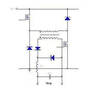
In the conventional two-switch forward arrangement, both switches operate together, and reset diodes return magnetizing energy to the input. Ideal switch voltage stress is approximately the input bus voltage, with practical overshoot and design margin added. A single-switch forward with an equal-turn reset winding has a different stress profile, approximately twice the input bus before parasitic overshoot. This is why comparisons should identify the actual circuit variant.
Ripple and transient response are separate requirements
A forward output inductor can reduce the ripple-current burden on the output capacitor relative to a basic flyback delivering pulsed secondary current. That is a useful design advantage, but it does not establish a universal output-ripple number. Capacitor ESR, switching frequency, layout, load current, and any additional filter remain important.
A load-step test answers a different question. When a valve bank turns on, the output capacitor initially covers the difference between load demand and converter current. The control loop must then adjust delivered power. Record voltage undershoot, overshoot after load removal, and recovery time under a defined current step and slew rate.
Do not accept “forward is more stable” as a substitute for those results. Likewise, a flyback should not be rejected without checking its tested transient performance.
Test from minimum to maximum input and repeat at low and high temperature. Use the actual load or an electronic load programmed with the same current step and slew rate. Capture input voltage, local output voltage, load-terminal voltage, and current on the same timebase. If the converter output remains steady but the load voltage falls, investigate wiring and connectors. If both fall while input remains steady, current limit, output impedance, or loop response becomes more likely. Repeated collapse and restart points toward protection or bias-supply behavior rather than ordinary transient recovery.
Multiple outputs and power factor need careful qualification
Adding secondary windings makes a flyback attractive for several isolated rails, but only the sensed output or feedback combination is directly regulated. Other rails can vary with diode drops, winding resistance, leakage, and the distribution of load. Weighted feedback trades error between outputs; it does not independently hold every output exactly at its target.
For a 24 V main rail and a 5 V auxiliary rail, test combinations such as an idle main output with a heavily loaded auxiliary output, then reverse the loading. A preload or a post-regulator may be needed if the required tolerance cannot otherwise be met. Forward converters can also supply multiple outputs, provided their filtering and regulation are designed accordingly.
Specify each rail's minimum and maximum load independently. Balanced-load testing can hide the worst cross-regulation case. Pay particular attention to diode drops on low-voltage rails, winding resistance on high-current rails, and the load required to keep an auxiliary output within range. If two rails both require tight accuracy over unrelated load profiles, a secondary regulator may be more predictable than trying to correct every combination through transformer turns and weighted feedback.
AC input power factor is a separate system property. DCM operation by itself does not guarantee unity power factor: the rectifier, input capacitor, and control method determine how mains current is drawn. A forward stage can sit behind a dedicated PFC stage, while a flyback can be designed specifically for single-stage PFC. Request power-factor and harmonic-current results at relevant line voltages and loads.
A single number measured at full load is not enough for equipment that spends most of its time lightly loaded. Ask for power factor, total harmonic distortion, efficiency, and standby consumption at the operating points that matter to the application. Also confirm whether the quoted result includes an external filter or front-end stage. The isolated DC-DC topology alone does not describe the complete AC input behavior.
What to request before approving a supply
A useful supplier comparison puts each candidate under the same conditions. A room-temperature efficiency figure cannot resolve whether a supply will support the required current in a sealed cabinet.
| Verification item | Evidence to request | Application relevance |
|---|---|---|
| Continuous output | Derating curve with mounting orientation and airflow conditions | Establishes usable current at the intended ambient temperature |
| Load transients | Waveforms with current-step size, slew rate, and recovery time | Shows whether switching loads can disturb control electronics |
| Ripple and noise | Results with stated bandwidth and probing method | Allows a meaningful comparison between suppliers |
| Multiple outputs | Voltage limits across unequal loading combinations | Reveals auxiliary-rail drift hidden by balanced-load tests |
| Overload and restart | Current-limit behavior and recovery under the intended load | Helps avoid repeated startup or nuisance shutdown |
| Isolation and EMC | Reports applicable to the exact model and intended installation | Confirms evidence relevant to equipment integration |
For engineering reviews, also request switch-stress and thermal results at the worst relevant input conditions. For purchasing reviews, keep the approved model, revision, and test conditions together so a later substitution can be assessed against the same requirements.
Choose the topology around the operating conditions
Flyback offers a compact route to isolation and additional outputs. Forward uses direct on-time power transfer and an output inductor, which can make it attractive for sustained current delivery. The practical decision rests on thermal performance, voltage behavior, and total implementation cost.
When discussing a supply with SIPURUI, share the input range, required output current, load-step profile, cabinet temperature, and installation constraints. Ask for model-specific evidence against those requirements. That gives both the engineer and the buyer a clearer basis for selection than a fixed wattage rule.