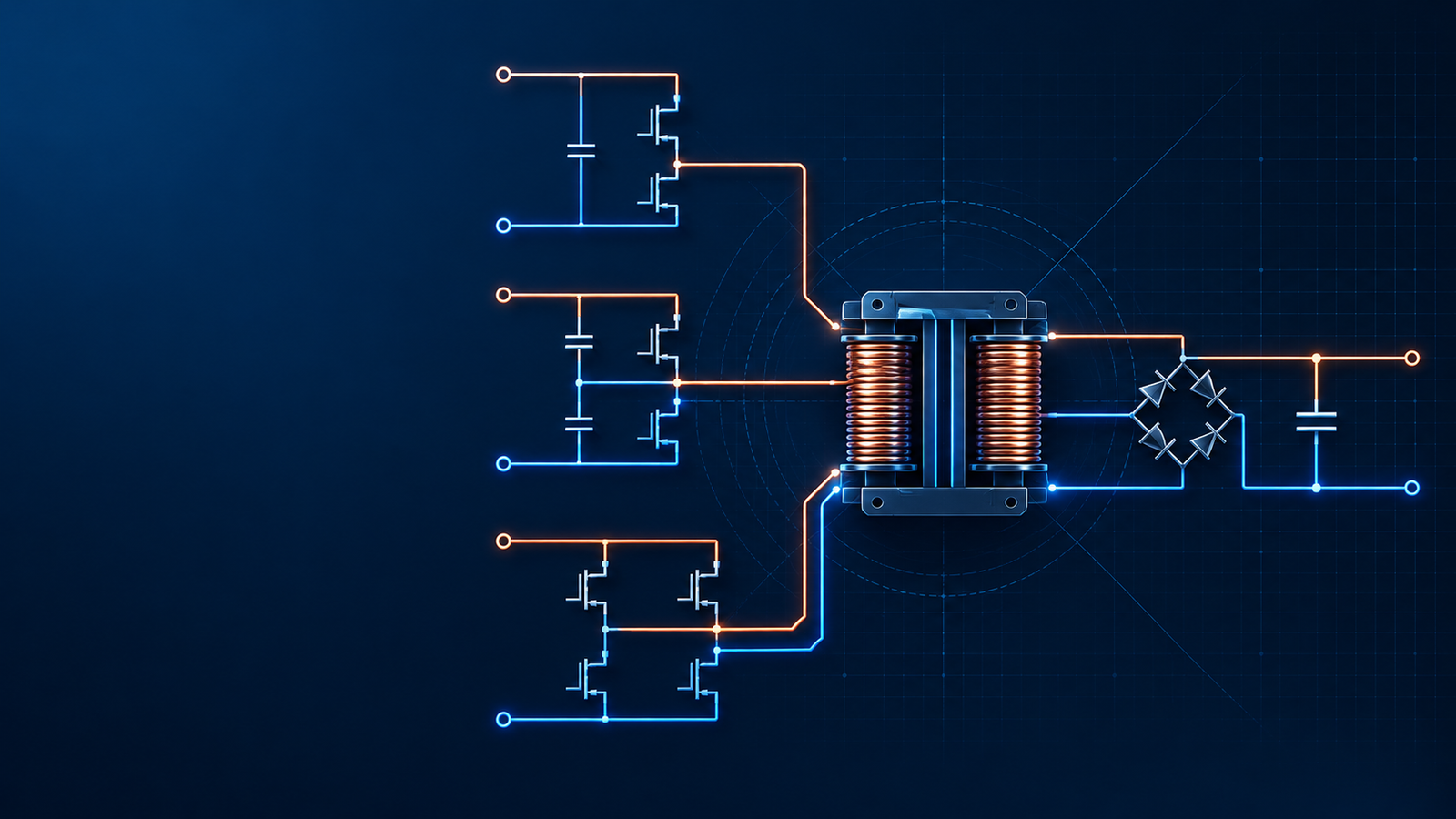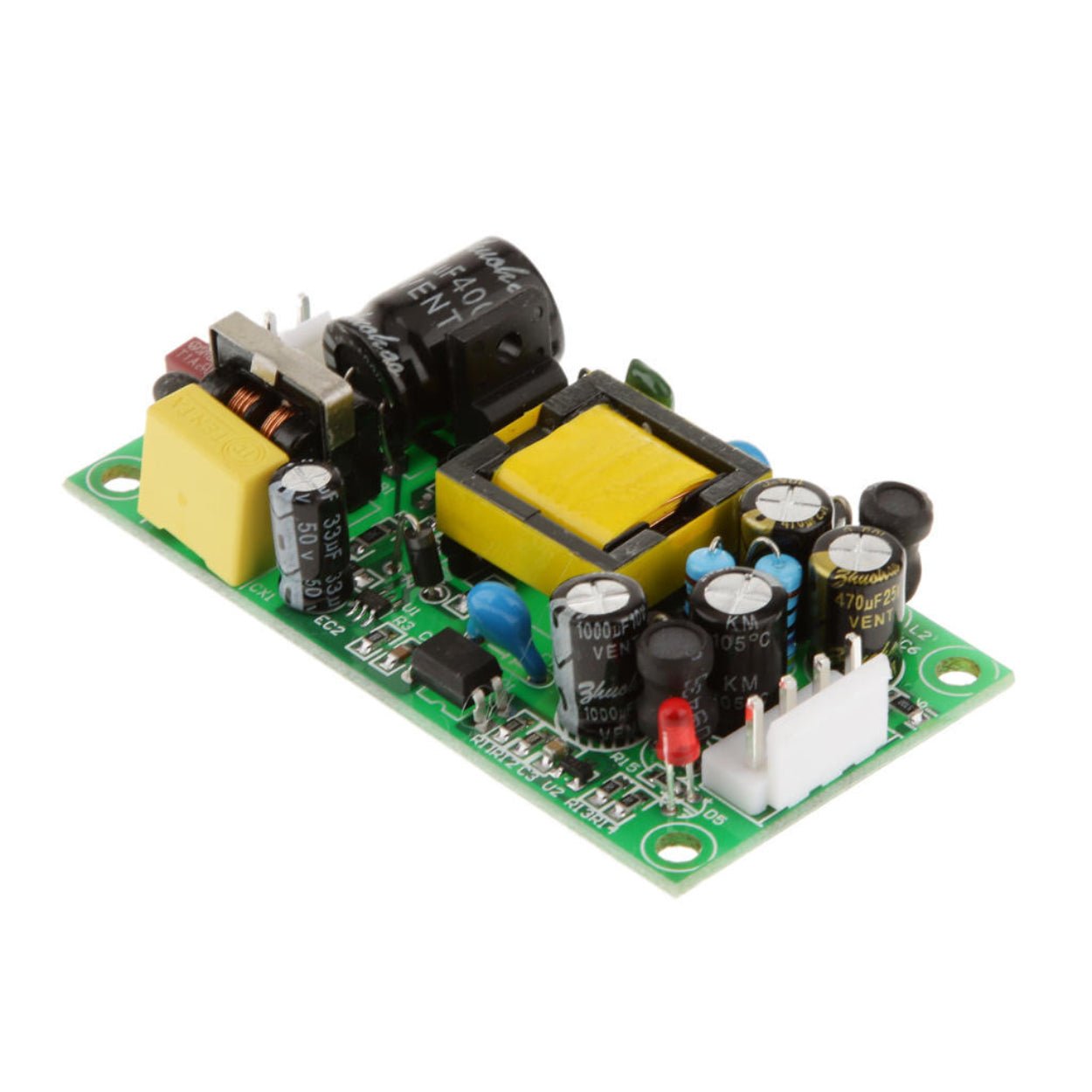
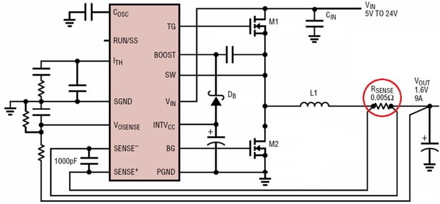
Switch Mode Power Supplies (SMPS) are the backbone of modern electronics-from industrial control systems to consumer adapters and high-power telecom equipment.
Overview
A Practical Engineering Guide to OCP Methods, Circuits, and Design Trade-Offs
Switch Mode Power Supplies (SMPS) are the backbone of modern electronics-from industrial control systems to consumer adapters and high-power telecom equipment. But what happens when something goes wrong?
What if the output is short-circuited?What if the load suddenly draws excessive current?What if a MOSFET is pushed beyond its safe operating area?
Without a well-designed overcurrent protection (OCP) system, the consequences are not just component failure-but potential system shutdown, fire hazards, or even safety risks to users.
So the real question is:
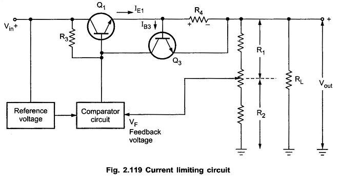
How do engineers design reliable, efficient, and accurate overcurrent protection in modern SMPS?
In this article, we break down the most widely used OCP methods, analyze their circuit implementations, compare their trade-offs, and explain how SIPURUI power supply designs approach protection at a practical level.
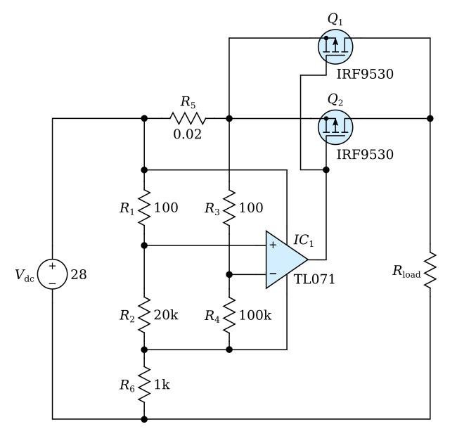
Why Is Overcurrent Protection So Critical in SMPS?
Overcurrent protection is not just a "safety feature"-it is a core reliability mechanism.

When abnormal current occurs, the power supply must:
Limit current immediately
Prevent thermal runaway
Protect switching devices (MOSFETs, diodes, transformers)
Avoid damage to downstream loads
In SIPURUI switching power supplies, OCP is always integrated alongside:
Overvoltage protection (OVP)
Overtemperature protection (OTP)
Short-circuit protection (SCP)
Because in real-world applications, these faults often occur simultaneously.
What Types of Overcurrent Protection Exist?
Before diving into circuits, let's understand the behavioral characteristics of OCP.
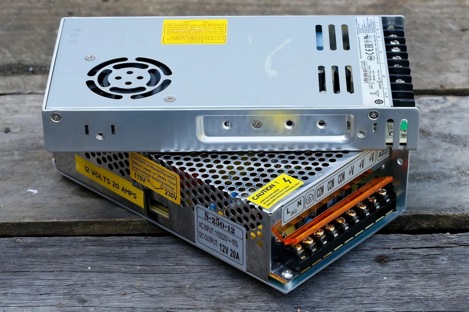
Three Typical OCP Modes
| Protection Type | Behavior Description | Typical Applications |
|---|---|---|
| Foldback (Droop) | Output voltage decreases as current increases | General SMPS (most common) |
| Constant Current | Current is clamped at a fixed level | LED drivers, battery chargers |
| Constant Power | Power remains constant as voltage drops | Specialized industrial systems |
In most SIPURUI AC-DC power modules, foldback current limiting is preferred because it balances:
Efficiency
Safety
Load compatibility
How Do Engineers Detect Overcurrent?
The key to OCP is current sensing.
But how do you measure current in a fast-switching circuit?
There are three mainstream approaches:
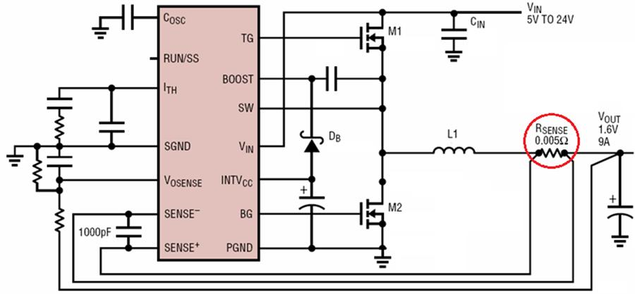
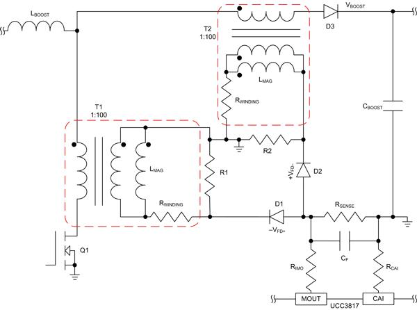
Shunt resistor sensing
Current transformer sensing
Indirect sensing via control IC
Let's explore them one by one.
Simple, Fast, But at What Cost?
This is the most commonly used method in SMPS designs.
How Does It Work?
A small resistor (Rsc) is placed in series with the MOSFET source or current path.
When current flows:
A voltage drop develops across Rsc
This voltage is monitored
Two Implementation Variants
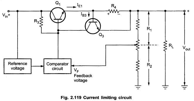
Transistor Trigger Method
Uses Vbe (~0.7V) as threshold
Simple but less accurate
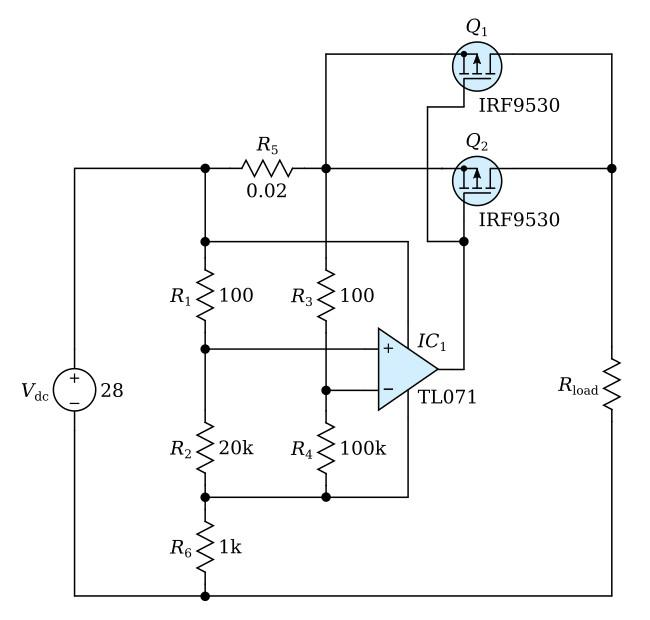
Comparator-Based Method
Uses precise reference voltage (100-200mV typical)
Faster and more stable
Transistor Trigger Method
Comparator-Based Method
Engineering Trade-Offs
| Parameter | Transistor Method | Comparator Method |
|---|---|---|
| Accuracy | Low | High |
| Response Speed | Medium | Fast |
| Cost | Very Low | Moderate |
| Efficiency Impact | Medium | Lower |
Key Design Insight
In wide input voltage systems (90-264VAC), primary peak current varies significantly.
This causes OCP threshold drift.
Solution used in SIPURUI designs:
Add biasing network from high-voltage rail
Stabilize detection threshold across line variations
Can We Combine Isolation and Protection?
In some SMPS topologies, the control circuit and output share a ground.
This allows direct integration of protection into the driver stage.
How Does It Work?
Load current flows through sensing resistor
Voltage triggers a transistor
A capacitor introduces delay
Control signal is suppressed
Why Add an RC Network?
Because not all current spikes are faults.
Startup surge
Transformer magnetizing current
Load transients
RC filtering ensures:
No false triggering
Controlled response time
Design Equation
Time constant:
τ=R×C\tau = R \times Cτ=R×C
Choosing τ correctly is critical:
Too small → false trips
Too large → slow protection
Can We Eliminate Power Loss?
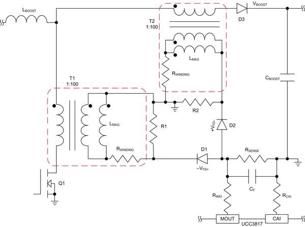
Yes-and that's where CT-based sensing shines.
Why Use a Current Transformer?
Unlike shunt resistors:
No direct power dissipation
Ideal for high-current systems
Working Principle
Steps:
Primary current flows through transformer
Secondary produces proportional current
Signal is rectified and filtered
Compared against threshold
Advantages vs Disadvantages
| Feature | CT Method |
|---|---|
| Power Loss | Very Low |
| Accuracy | High (if well designed) |
| Complexity | High |
| Cost | Higher than resistor |
| Calibration | Required |
Critical Design Considerations
Core saturation
Turns ratio accuracy
Frequency response
Layout parasitics
In SIPURUI industrial SMPS units (especially >300W), CT sensing is often used to:
Improve efficiency
Reduce thermal stress
Maintain stable protection across loads
What Happens After Overcurrent Is Detected?
Detection is only half the story.
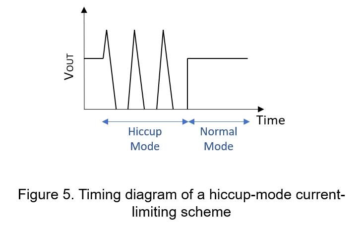
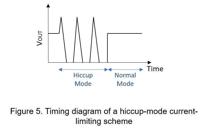
Enter Hiccup Mode
Instead of shutting down permanently:
Power turns OFF
Waits for a delay
Attempts restart
Repeats if fault persists
Why Use 555?
Because it provides:
Built-in comparators
RS latch
Timing control
Behavior During Fault
| Phase | Description |
|---|---|
| Normal | PWM switching active |
| Overcurrent | Detection triggers shutdown |
| Delay | RC timing holds OFF state |
| Restart | System attempts recovery |
| Loop | Repeats if fault remains |
Key Benefit
Thermal protection through duty cycling
Instead of continuous stress:
ON time = short
OFF time = long
This dramatically reduces heat.
Why SIPURUI Uses Hiccup Mode
In many SIPURUI AC-DC power supplies:
Prevents catastrophic failure
Enhances long-term reliability
Ensures safe auto-recovery
Which OCP Method Is Best?
Let's compare them clearly.
Comprehensive Comparison Table
| Method | Efficiency | Accuracy | Cost | Complexity | Best For |
|---|---|---|---|---|---|
| Shunt + Transistor | Medium | Low | Low | Low | Low-cost adapters |
| Shunt + Comparator | High | High | Medium | Medium | General SMPS |
| CT Sensing | Very High | High | High | High | High-power systems |
| 555 Hiccup | High | Medium | Low | Medium | Robust protection designs |
How Do SIPURUI Power Supplies Optimize OCP?
Instead of relying on a single method, modern designs combine techniques.
Typical SIPURUI Strategy
Primary cycle-by-cycle current limiting (fast response)
Secondary protection (backup)
Hiccup mode for sustained faults
Thermal protection integration
Example: SIPURUI Industrial SMPS Design
| Feature | Implementation |
|---|---|
| Current Detection | Shunt + Comparator |
| High Power Models | CT-assisted sensing |
| Fault Response | Hiccup mode |
| Protection Threshold | 110%-130% rated current |
| Recovery | Automatic |
What Should Engineers Pay Attention To?
Even with the right method, poor implementation leads to failure.
Key Design Pitfalls
Threshold Drift
Line voltage changes → current changes → false protection
Noise Sensitivity
Switching noise can trigger false OCP
Slow Response
Too much filtering delays protection
Thermal Coupling
Hot resistors change sensing accuracy
Threshold Drift
Noise Sensitivity
Slow Response
Thermal Coupling
Practical Engineering Advice
Always validate with real load testing
Measure peak current, not average
Test across full input voltage range
Simulate worst-case fault scenarios
So-what is the best overcurrent protection method?
The honest answer:
It depends on your application.
Low-cost adapters → simple resistor sensing
Industrial systems → CT + digital control
Safety-critical → hiccup + multi-layer protection
At SIPURUI, we design protection systems not just to pass tests-but to survive real-world conditions.
Because a reliable power supply is not defined by how it works under normal conditions-
but by how it behaves when things go wrong.
Buyer Checklist
- Confirm input and output voltage before model selection.
- Check wattage, load margin and operating temperature.
- Review installation space, airflow and protection requirements.
- Share project quantity and application details for quotation support.