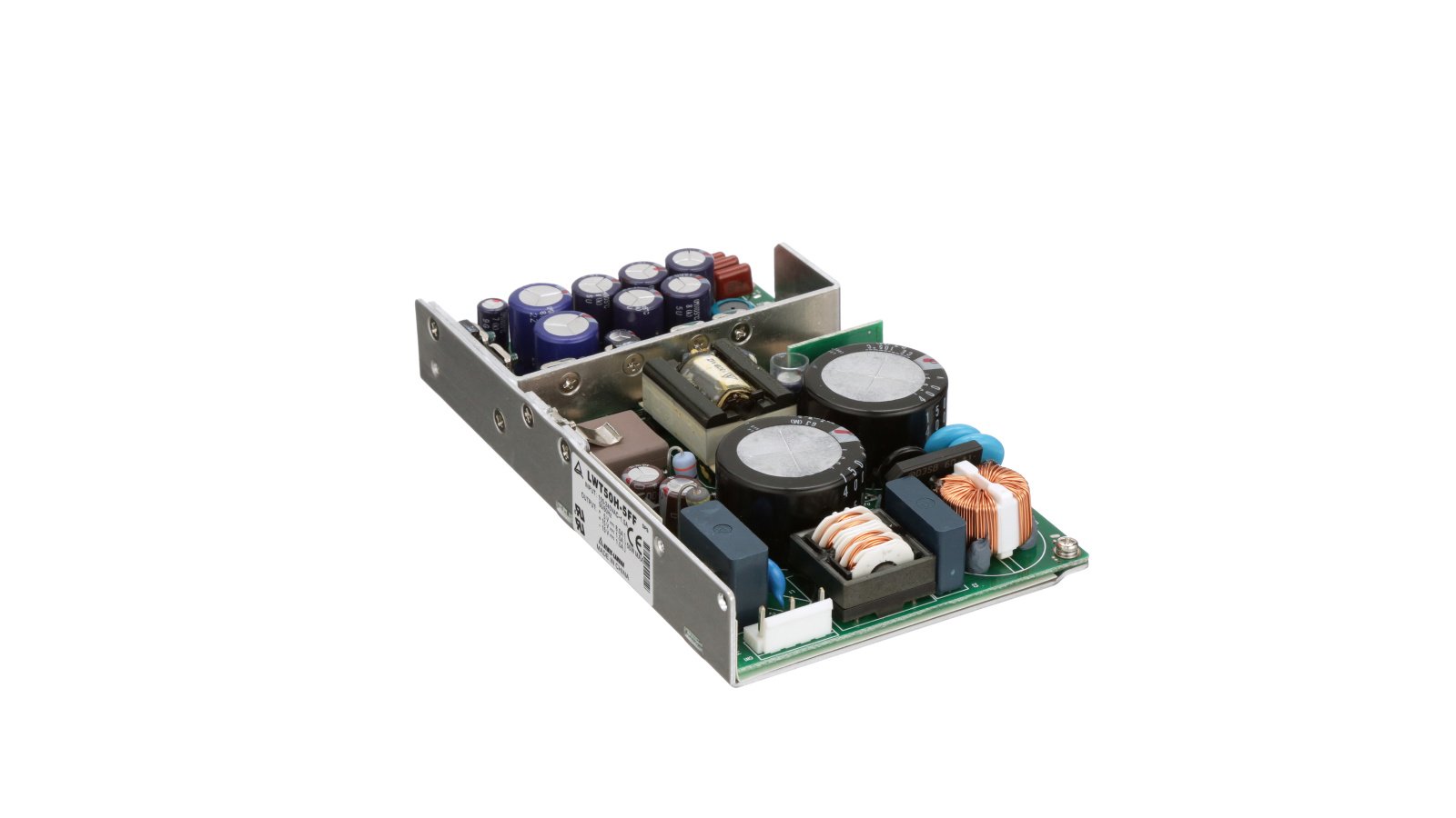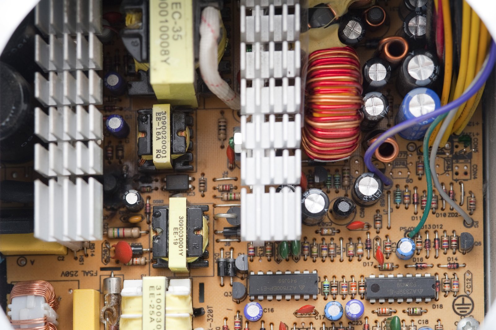
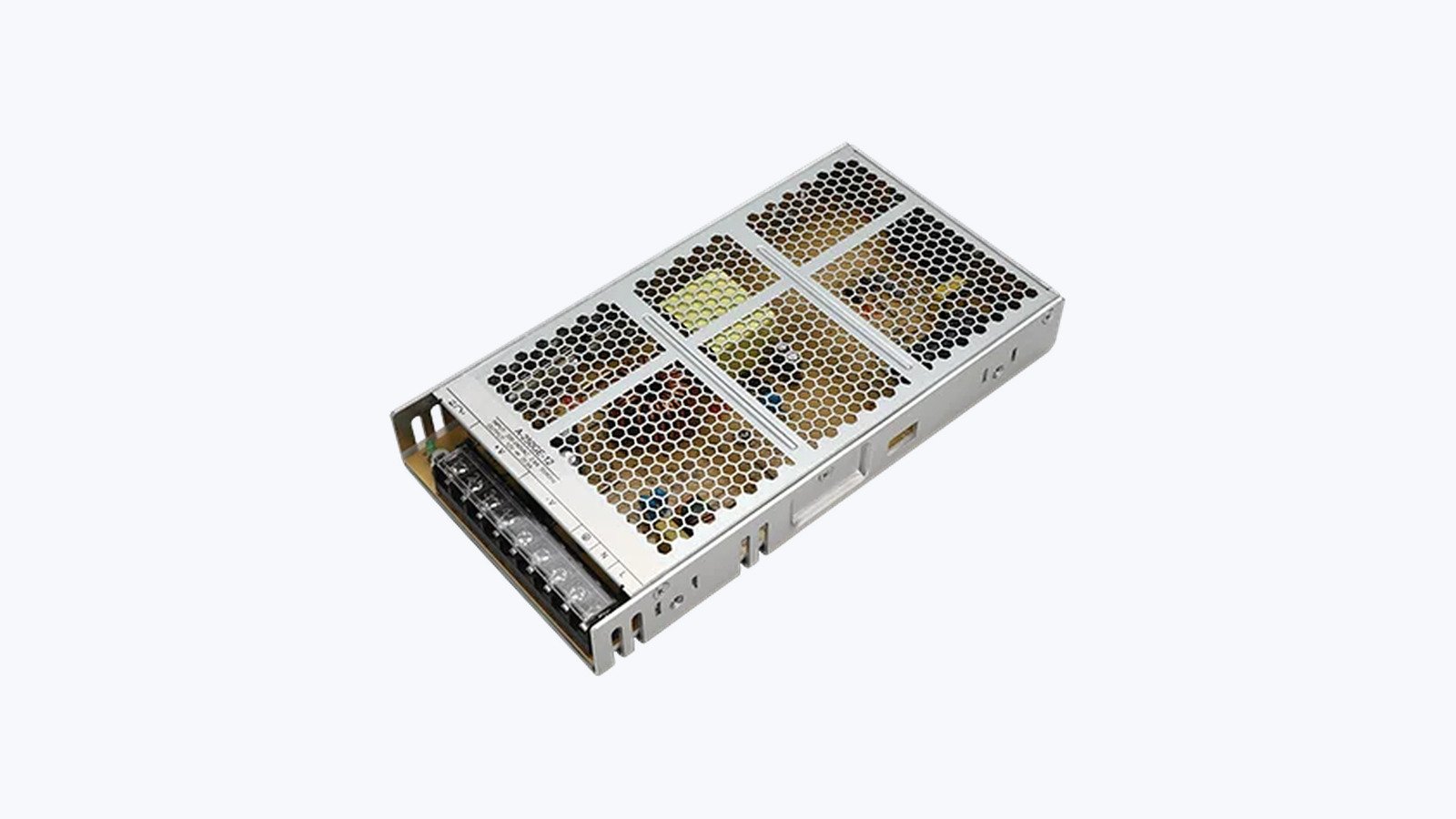
A switching power supply can draw a brief input pulse many times larger than its normal operating current. That pulse may be perfectly survivable for the power supply yet still open a fuse, trip a breaker, pit a relay contact, or pull down a shared AC branch. In other designs, the AC-input event is acceptable but the converter enters hiccup mode because a large output capacitor or downstream load demands too much current during startup.
A switching power supply can draw a brief input pulse many times larger than its normal operating current. That pulse may be perfectly survivable for the power supply yet still open a fuse, trip a breaker, pit a relay contact, or pull down a shared AC branch. In other designs, the AC-input event is acceptable but the converter enters hiccup mode because a large output capacitor or downstream load demands too much current during startup.
These are related problems, but they are not the same problem. Effective suppression starts by identifying where the current flows and when it occurs. The input bulk capacitor needs a precharge path. The PFC and DC-DC stages need a controlled takeover. The output needs a ramp and current limit that can charge the real capacitive load. Multi-output systems may also need sequencing. Treating every startup symptom as an NTC selection issue usually leaves one of those paths unaddressed.
Start by Separating the Current Events
The term *inrush current* is most useful when it refers to the short AC-input current that charges the high-voltage DC bus as the supply is connected to the line. Engineers also use the term more broadly for excessive current during power-stage startup and for the current needed to charge output capacitance. The three events can overlap in a waveform, but their controls are different.
| Current event | Main path | Typical symptom | Primary control |
|---|---|---|---|
| DC-bus precharge | AC source, rectifier, bulk capacitor | Fuse operation, breaker trip, rectifier or contact stress | NTC, precharge resistor with bypass, or active limiter |
| PFC or power-stage startup | PFC inductor, primary switches, transformer or resonant tank | Current-limit trip, switch stress, bus disturbance | Controller soft start, current limit, duty or frequency management |
| Output-capacitor charging | Secondary rectifier or synchronous FET, inductor, output capacitor | Slow ramp, hiccup, overshoot, failure to start a load | Controlled voltage ramp, constant-current limiting, load sequencing |
In a conventional bridge-and-capacitor front end, a discharged bulk capacitor initially presents a low impedance. The first pulse is limited by the instantaneous line voltage and the complete series impedance: mains source, wiring, EMI filter, switch or relay, rectifier, capacitor ESR, PCB resistance, and any intentional limiter. The pulse is therefore sensitive to AC phase and source impedance. Closing near the line peak on a stiff source is much more severe than closing near zero crossing through a long test lead.
Power-stage current begins later, when the controller reaches undervoltage-lockout release and starts switching. Output charging follows the controlled buildup of transferred energy. A current spike that appears after the bus has already charged should not automatically be blamed on the input NTC.
Estimate Energy Before Choosing a Limiter
For a first design pass, calculate the energy that the input limiter must manage:
E = 1/2 × Cbus × Vbus²
Consider a 100 W supply on 230 Vac with a 68 µF bulk capacitor. The rectified line peak is about 325 V, so the capacitor stores roughly 3.6 J when charged to the peak. That figure is useful for checking an NTC or precharge resistor pulse-energy rating. It does not, by itself, predict peak current.
An intentionally simplified peak-current estimate is:
Ipeak ≈ Vac,instantaneous / Rtotal
If a 10 Ω cold limiter dominated the path at a 325 V connection point, the first estimate would be about 32.5 A. Real waveforms differ because the capacitor voltage rises, the line changes, the rectifier conducts nonlinearly, and other impedances contribute. The estimate is still far more defensible than claiming a universal multiple of rated input current.
For procurement, a peak value without its test conditions is incomplete. At minimum, record line voltage and frequency, connection phase or test method, source impedance, ambient temperature, initial bus voltage, off-time before restart, peak current, pulse duration, and the measurement bandwidth.

Method 1: Use an NTC Where Starts Are Infrequent
An inrush-current-limiting NTC thermistor is the lowest-cost solution for many small and medium AC-DC supplies. It has relatively high resistance when cold. Load current heats it after startup, reducing its resistance and normal operating loss.
Select the part from its manufacturer data rather than from a generic disc-size table. The critical checks are:
Cold resistance at the lowest and highest specified ambient temperatures
Maximum continuous current after thermal derating
Maximum permitted capacitance or pulse-energy test condition
Maximum operating voltage and required safety spacing
Hot resistance and resulting steady-state dissipation
Thermal recovery time before the next protected start
TDK's inrush-limiter guidance notes that full resistance recovery can take one to two minutes, depending on the device. This is why a supply may start reliably from cold but trip protection after a short off-on cycle. High ambient temperature creates a similar weakness because the NTC begins with less resistance.
Do not parallel ordinary NTC limiters to increase current capacity. Small resistance differences cause the warmer device to take more current, heat further, and take still more current. Use a suitably rated part, a manufacturer-approved assembly, or a different limiting architecture.
An NTC also does not become a problematic inductor simply because the converter switches above 100 kHz. It sits in the low-frequency input path, while the EMI filter and converter layout determine most high-frequency current paths. The practical NTC concerns are thermal behavior, energy, voltage, loss, and restart performance.
Method 2: Add a Precharge Bypass for Higher Power or Frequent Starts
A fixed resistor or NTC can limit the first charging pulse, then a relay, triac, SCR, or MOSFET can bypass it after the DC bus is adequately charged. The bypass removes most steady-state dissipation and gives the designer more freedom to use a higher precharge resistance.
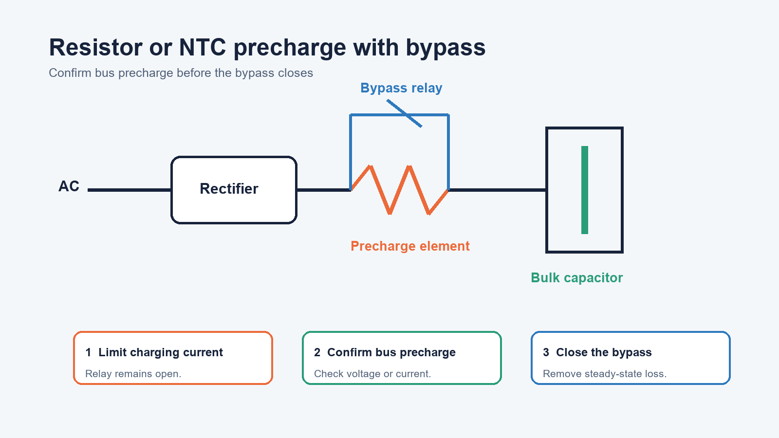
The precharge component must survive the single-pulse energy and the required repetition rate. A fixed resistor also needs an adequate voltage rating, creepage distance, and transient overload rating. The bypass device must carry the steady-state RMS current and tolerate the voltage and fault conditions present when open.
Control logic matters as much as component ratings. Close the bypass only after the bus voltage has reached a defined threshold or the charging current has fallen below a safe level. A blind one-second delay can work in a narrow design but provides no evidence that precharge actually succeeded. If the relay closes while the bus remains discharged, the circuit recreates the original inrush problem through the relay contacts.
Define failure behavior as well. Consider a relay that never closes, a welded contact, a chattering auxiliary supply, a brownout that partially discharges the bus, and an immediate restart. TI distinguishes the current following AC recovery from cold-start inrush as *re-rush*; modern data-center requirements increasingly specify this event because the bus and relay state may be different from a true cold start.
Method 3: Use Active Limiting for Precision and Hot-Plug Operation
Active circuits use a MOSFET or thyristor plus control circuitry to shape the charging current. They are attractive for hot-plug DC inputs, frequent cycling, redundant supplies, telecom equipment, and systems where a passive limiter cannot meet the loss or repeatability target.
Two control approaches are common. A gate-slew circuit limits output dV/dt; because capacitor current is I = C × dV/dt, a controlled voltage ramp controls charging current. A closed current loop measures a sense resistor and adjusts the pass FET directly. The second method is more precise when load capacitance and device gate characteristics vary.
The pass device must be checked against its safe operating area, not only its on-resistance. During precharge it can simultaneously support high drain-source voltage and substantial current for milliseconds or longer. A MOSFET with an excellent low-RDS(on) headline can still fail linear-mode stress. Thermal retry behavior, timer settings, reverse-current paths, and short-circuit response must be designed with the same care as the nominal current limit.
Coordinate the PFC Stage Instead of Treating It as a Second NTC Problem
In an active-PFC supply, the passive precharge path normally raises the bulk capacitor toward the rectified-line peak before PFC regulation takes over and boosts the bus toward its operating target. The PFC controller must then increase energy gradually. Current limiting, soft-start references, voltage-loop behavior, and relay timing all influence this transition.
There is no universal startup duty-cycle value such as 20% or 30% that fits every boost PFC. At low instantaneous line voltage, a boost stage may require a high duty ratio during normal operation. The safe approach is to follow the controller's startup method, inductor-current limit, brownout behavior, and application circuit, then verify the waveforms on the actual magnetics and bus capacitor.
For bridgeless or totem-pole PFC, precharge deserves special attention because switch body-diode and reverse-conduction paths differ from a diode bridge. A reference design may use an NTC and relay, a dedicated precharge branch, or controlled switching. Copy the complete startup sequence, not only the power-stage schematic.
Soft-Start the Main Converter According to Its Topology
Once the input bus is ready, the main converter should build output voltage without saturating magnetics, exceeding switch current, or repeatedly entering protection.
| Topology | Practical startup control | Design focus |
|---|---|---|
| Flyback or forward | Ramp the current command, feedback reference, or duty limit | Peak current, transformer flux reset, output overshoot |
| Buck | Program the SS pin or reference ramp and retain cycle-by-cycle current limit | Inductor current and capacitive-load charging |
| Boost | Coordinate duty command, current limit, and output prebias | Startup path exists even before active switching |
| LLC resonant | Start at a controller-defined high frequency and ramp toward regulation | Resonant current, capacitive-region avoidance, load-dependent timing |
| Phase-shifted full bridge | Ramp phase shift and current command | Transformer flux balance and circulating current |
LLC startup is frequently oversimplified. Many controllers begin at a high switching frequency, where the resonant tank transfers less energy, and then ramp toward the operating range. That does not guarantee zero-voltage switching under every startup condition, nor does it remove the need for overcurrent protection. STMicroelectronics notes that increasing frequency helps control tank current but may not limit short-circuit output current sufficiently on its own. The controller's capacitive-region avoidance and measured resonant waveforms remain important.
Soft-start time should be derived from the available charging current and load, not selected only from a typical RC value. A useful output-side relationship is:
Icap = Cout × dVout/dt
If a 12 V rail with 2,200 µF must rise in 20 ms, the capacitor alone requires an average 1.32 A. Add the load current that is already active during the ramp. If the total exceeds the converter's startup current capability, the output will ramp slowly, enter constant-current operation, or hit hiccup protection.
Make Output Current Limit and Capacitive Load Work Together
Hiccup protection is valuable for sustained faults, but it can prevent a legitimate capacitive load from ever charging. Each attempt transfers a small packet of energy; the output then discharges before the next attempt. Constant-current startup or a longer soft-start ramp often works better when the load capacitance is intentional.
Do not rely on a generic rule that startup OCP must be 2.0 to 2.5 times rated current. The correct threshold depends on switch and magnetic limits, output capacitance, load behavior, ramp time, tolerance, and thermal retry conditions. Some controllers provide a startup-specific current profile. Others use the same cycle-by-cycle limit in startup and steady state. Verify the exact controller behavior rather than assuming a two-level OCP feature.
Also check prebiased outputs. Synchronous converters may sink current or discharge an existing output if their startup logic is not prebias-safe. That can create an unexpected current path even when the intended load is modest.
Sequence Multiple Rails and Multiple Power Supplies
Startup coordination becomes a system problem when several rails or several complete supplies share one input branch. Enabling every rail simultaneously adds their output-charging demands. Closing a cabinet contactor onto ten AC-DC supplies can align their input precharge pulses closely enough to trip a breaker even if every unit passes its individual inrush test.
Sequence downstream rails with enable and power-good signals when the load permits it. At the AC system level, stagger supply groups or choose a centralized precharge architecture. The interval must be based on measured startup completion, not an arbitrary number of milliseconds. Account for the slowest valid startup at low line, high load, and temperature extremes.
Select the Architecture from the Application
| Application condition | Likely starting point | Qualification priority |
|---|---|---|
| Small adapter, infrequent start | Series NTC | High-line cold start and hot-ambient start |
| Industrial supply, moderate or high power | Resistor or NTC with bypass | Relay timing, abnormal precharge, restart |
| 24 V or 48 V hot-plug module | MOSFET hot-swap controller | FET SOA, dV/dt, current-loop stability |
| High-power PFC front end | Dedicated precharge plus controlled PFC takeover | Brownout recovery, relay state, inductor current |
| Large external output capacitance | Slow ramp or constant-current startup | Charge time, hiccup interaction, connector current |
| Many supplies on one breaker | Per-unit limiting plus staggered start | Branch impedance and breaker instantaneous curve |
The choice is not determined by power rating alone. Start frequency, efficiency target, ambient range, available control power, safety requirements, restart interval, and acceptable failure modes may push two supplies of the same wattage toward different solutions.
Measure the Waveform That the System Actually Sees
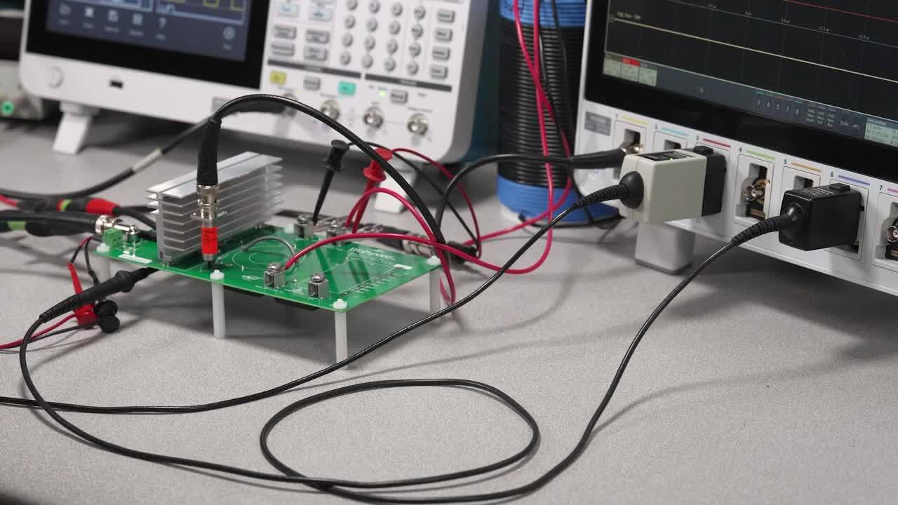
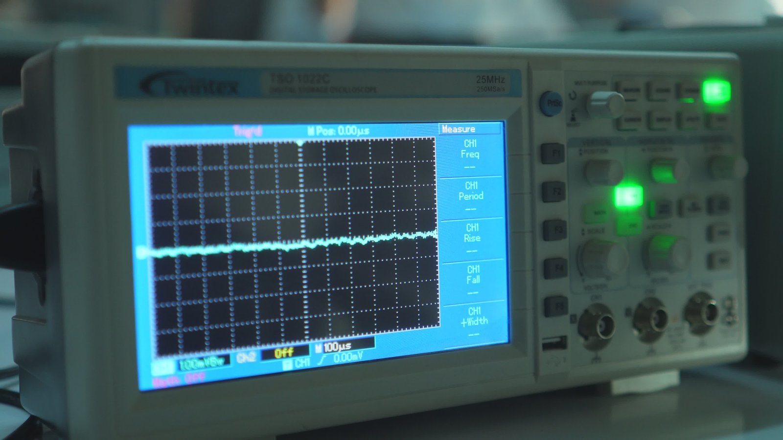
Use a rated current probe or a properly specified shunt and isolated measurement system. Do not connect a grounded oscilloscope probe directly to a non-isolated primary node. For AC input testing, single-shot acquisition triggered from the line switch, relay command, or input-current threshold is usually more reliable than triggering from a controller enable signal that occurs after bus precharge.
Capture more than one time scale. A microsecond-scale view reveals peak current and ringing. A millisecond-to-second view shows bus charging, relay closure, PFC takeover, output ramp, and protection retries. Record bus voltage and input current together when possible.
Run at least these cases:
High-line cold start at the lowest expected source impedance
High-ambient start for an NTC-based design
Rapid off-on restart across a range of off-times
Brownout and AC recovery while the load remains connected
Maximum external output capacitance and startup load
Simultaneous and sequenced startup of the complete cabinet or rack
Single-fault conditions relevant to the precharge and bypass circuit
Compare measured peak current and pulse I²t with the bridge rectifier surge rating, fuse time-current data and pre-arcing I²t, relay or switch capability, limiter energy rating, PCB path, and upstream breaker curve. A target such as “no more than twice rated input current” may be desirable, but it is not a universal quality threshold. A higher, shorter pulse can be safe and compliant if every component and protection device is coordinated for it.
A Practical Design Checklist
Identify whether the failure occurs at line connection, converter enable, or output rise.
Calculate DC-link energy and output-capacitor charge demand.
Define cold-start, hot-restart, and brownout-recovery requirements.
Select NTC, bypass precharge, or active limiting from repetition rate and loss constraints.
Use voltage or current feedback to confirm precharge before bypass where reliability matters.
Follow the PFC and DC-DC controller's documented startup sequence.
Check active pass devices in linear-mode SOA.
Coordinate output soft start with load current, capacitance, and OCP mode.
Test the assembled system with its actual breaker, contactor, wiring, and number of supplies.
Record the waveform and test conditions in the product specification.
Conclusion
Inrush suppression is not a single component choice. The input limiter controls DC-bus charging; the PFC and main converter control how switching begins; the output ramp controls capacitive-load current; and system sequencing prevents several acceptable events from becoming one unacceptable event.
The most reliable design is the one whose startup waveform is predictable across line, temperature, restart interval, load, and production tolerance—and whose energy and I²t are coordinated with the real fuse, rectifier, switch, relay, MOSFET, and breaker. SIPURUI can support OEM power-supply selection and application review when inrush current, capacitive loads, cabinet startup, or protection coordination is part of the specification.