Industrial test equipment often needs several supply rails in a space that was sized for one. A controller may require 5 V, analog front ends may need ±12 V, relays or sensors may need 9 V, and an isolated interface may have its own 6 V rail. The difficult part is not creating each voltage on a bench. It is delivering all of them from the AC line while controlling startup, cross-regulation, noise, safety spacing and abnormal conditions as one system.
Overview
Industrial test equipment often needs several supply rails in a space that was sized for one. A controller may require 5 V, analog front ends may need ±12 V, relays or sensors may need 9 V, and an isolated interface may have its own 6 V rail. The difficult part is not creating each voltage on a bench. It is delivering all of them from the AC line while controlling startup, cross-regulation, noise, safety spacing and abnormal conditions as one system.
This guide develops a practical architecture for a compact module with 85–264 VAC input and nominal +5 V, +6 V, +9 V and ±12 V outputs. It also shows how to switch selected rails from external logic and how to set meaningful undervoltage and overvoltage protection. The exact current ratings must come from the equipment load budget, so the design process begins there rather than with a transformer or controller part number.
Start With the Rail Budget and Operating States
Create a rail table that covers steady load, peak load, startup current, allowable ripple and whether a rail must be controllable. A “5 V, 2 A” label is incomplete if the load draws 3.5 A for 20 ms at power-up. Likewise, the ±12 V rails may look lightly loaded in total watts but still require tight symmetry for an analog measurement path.
| Rail | Typical load role | Regulation focus | Control requirement |
|---|---|---|---|
| +5 V | MCU, digital I/O, logic | Tight static accuracy and low transient dip | Often switchable or sequenced |
| +12 V / −12 V | Op-amps, analog conditioning, interfaces | Cross-regulation, symmetry, low noise | May need simultaneous enable |
| +9 V | Reference or intermediate analog rail | Low drift and low ripple | Usually always on |
| +6 V | Isolated interface, sensor or local post-regulator input | Isolation and startup behavior | Application dependent |
Separate “always-on” power from “switched” power. An always-on housekeeping rail can run the control and fault logic while load switches or downstream DC/DC enable pins connect the higher-current rails only after the system is ready. This is usually easier to validate than repeatedly stopping and restarting the complete offline converter.
Choose an Architecture That Matches the Loads
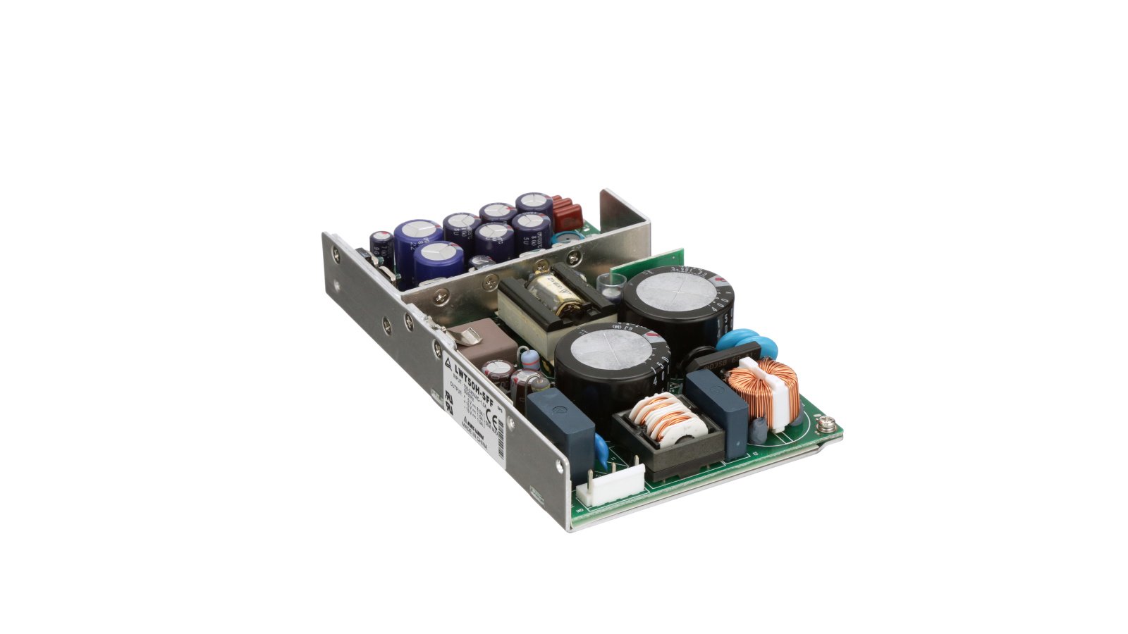
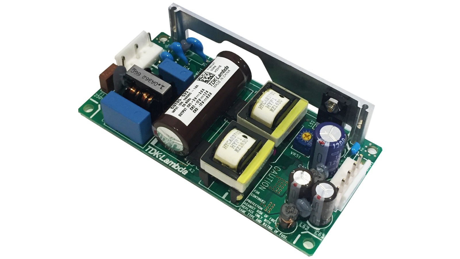
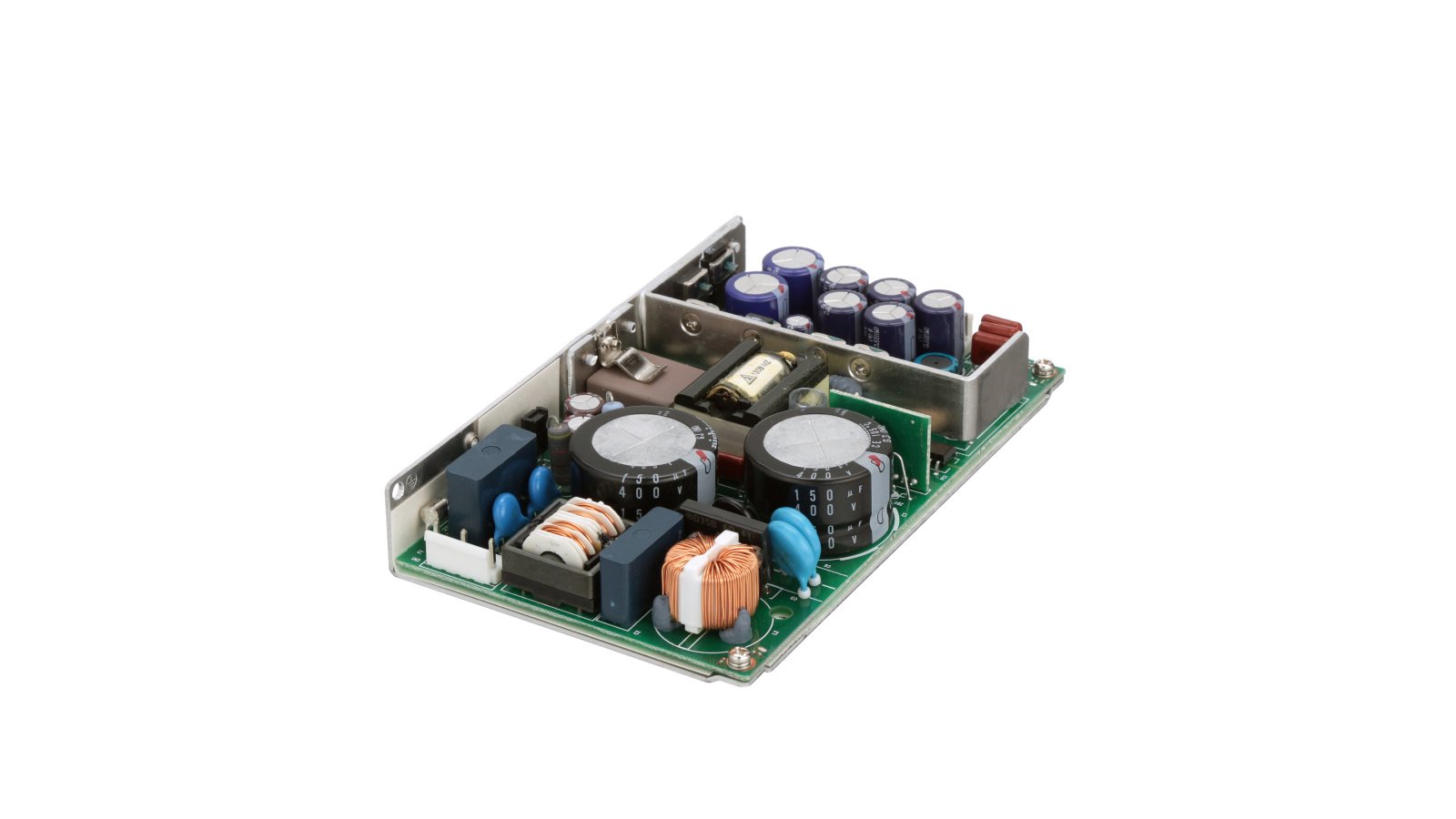
For a compact module below roughly 60–80 W, an isolated flyback is often a sensible starting point because a custom transformer can supply several secondary windings. A published 25 W Texas Instruments reference design demonstrates seven outputs and multiple isolated grounds from one quasi-resonant flyback, while the Cincon CFM60T commercial family provides triple outputs such as 5 V, +12 V and −12 V. These examples show feasibility, not a drop-in design; transformer construction, regulation and safety approval remain specific to the final product.
There are three useful patterns:
| Architecture | Best fit | Main tradeoff |
|---|---|---|
| Multi-winding flyback | Moderate power, compact board, related rails | Lowest part count, but weaker cross-regulation on lightly loaded outputs |
| Main isolated rail plus secondary buck/LDO stages | Tight low-voltage rails and changing loads | Better regulation; more components and conversion loss |
| Several isolated converters | Independent grounds or strict fault containment | Strong isolation between loads; highest cost and area |
The source material used a rectified high-voltage bus for the main converter and a separate line-frequency transformer for low-voltage control rails. That can work, but two magnetic conversion paths increase volume and assembly effort. In a new design, compare it with a single safety-approved offline stage plus secondary post-regulators. Retain the separate transformer only when it solves a real requirement such as standby loss, independent isolation, legacy qualification or exceptionally quiet analog power.

Design the AC Front End as a Safety Function
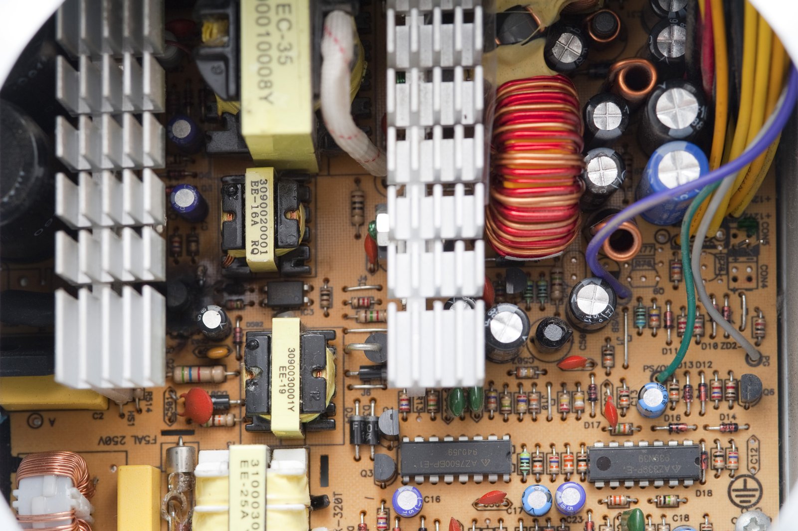
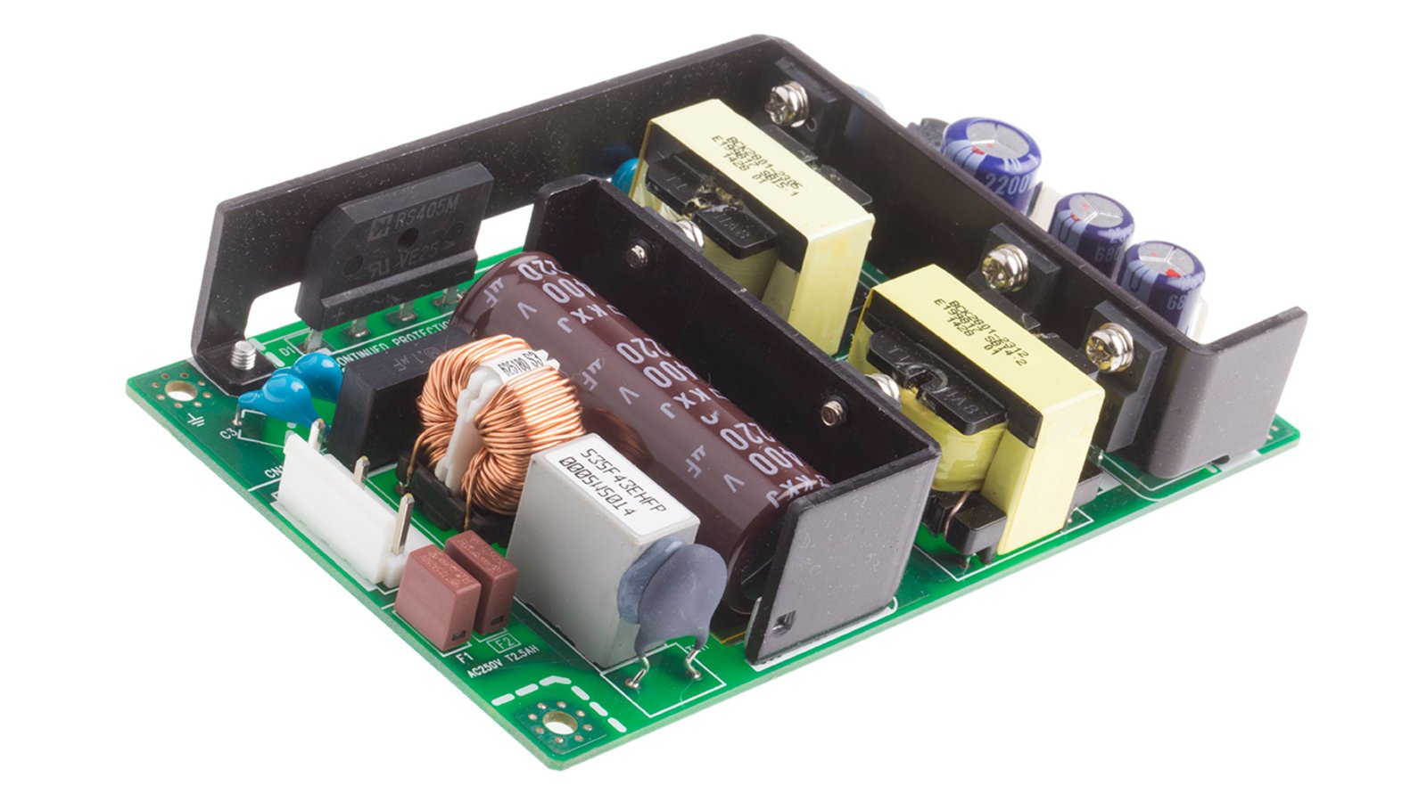
The mains path should include a correctly rated fuse, surge limiting, inrush control, an EMI filter, bridge rectifier and bulk capacitor. At 230 VAC, the rectified bus is approximately 325 VDC at the waveform peak, not simply “300 V.” Component voltage ratings must also cover high-line input, tolerance and transients.
The EMI filter should be selected from conducted-emission test results, not copied from another power level. A common-mode choke and Y capacitors address common-mode noise; an X capacitor and differential inductance address differential-mode noise. Leakage current, discharge resistors and the equipment’s protective-earth arrangement constrain the capacitor values. If an off-the-shelf inlet filter is used, confirm its current rating, temperature range, safety approvals and the effect of downstream wiring on performance.
Keep the high di/dt primary loop tight: bulk capacitor, transformer primary, switching device and current-sense return. Maintain the required creepage and clearance between primary and secondary copper, transformer pins, optocoupler pins and mounting hardware. Slots can help, but they do not correct a poor isolation plan.
Regulate Multiple Outputs Without Hiding Cross-Load Problems
Only one flyback output normally closes the main feedback loop. The other windings follow through turns ratio and transformer coupling, so their voltage changes with load distribution, diode drop and winding resistance. This is why a multi-output supply can meet specification at full balanced load yet exceed tolerance when the main rail is lightly loaded and an auxiliary rail is heavily loaded.
Use the most critical and consistently loaded rail as the feedback rail. Add minimum-load resistors only after measuring the loss penalty. For precision rails, use a secondary buck converter or LDO; an LDO is attractive for low noise when the input-output headroom and thermal dissipation are acceptable. A 9 V reference rail derived from 12 V, for example, can be quiet and accurate at modest current, but the regulator must survive the highest possible 12 V rail during fault and cross-load conditions.
For bipolar ±12 V rails, check both magnitude and tracking. If the loads are strongly unbalanced, separate regulation or a dedicated bipolar DC/DC stage can be more predictable than two loosely coupled transformer windings.
Control Selected Outputs Through an Isolated Enable Path
External high/low control should not compromise the isolation barrier or create an undefined startup state. An optocoupler or digital isolator can transfer the command, while a load switch, MOSFET stage or downstream converter enable pin controls the rail. Define the polarity and the open-circuit behavior: equipment should not energize a hazardous or sensitive load because a connector is unplugged.
If +12 V and −12 V supply the same analog section, enable them together and measure skew. Add output discharge where stored energy would keep a circuit partially powered. Check current paths through signal protection diodes; a disabled rail can otherwise be back-powered from an active data line.
Six optocoupler outputs, as mentioned in the original concept, can report rail-good or fault states, but each channel needs a threshold, polarity, propagation-time allowance and default state. “Power good” should mean that the rail is inside its validated window, not merely that some voltage is present.
Coordinate Undervoltage, Overvoltage and Short-Circuit Protection
Set protection thresholds outside the complete normal tolerance band. That band includes converter set-point error, line and load regulation, ripple, temperature drift, component aging and measurement tolerance. A threshold placed too close to nominal will chatter; one placed too far away may not protect the load.
| Fault | Detection point | Preferred response | Validation question |
|---|---|---|---|
| Input undervoltage | Controller UVLO or DC-bus divider | Inhibit with hysteresis | Does the module avoid repeated high-current restart? |
| Output undervoltage | Rail supervisor | Disable dependent loads; report fault | Is a heavy transient mistaken for a persistent fault? |
| Output overvoltage | Independent supervisor or OVP pin | Latch-off, clamp or crowbar as risk requires | Does protection still work if feedback opens? |
| Short circuit / overload | Primary current limit and rail protection | Hiccup or constant-current limit | Are connectors and rectifiers safe during repeated faults? |
| Overtemperature | Hotspot sensor or controller protection | Derate or shut down | Is recovery controlled, not oscillatory? |
An overvoltage monitor that uses the same reference and feedback path as the regulator is not fully independent. For a rail that can damage expensive test hardware, consider a separate supervisor and a protection mechanism capable of removing energy. Coordinate the secondary action with primary-side overload and loss-of-feedback protection so the supply cannot cycle indefinitely into a destructive condition.
Treat Layout and Thermal Design as Part of the Circuit
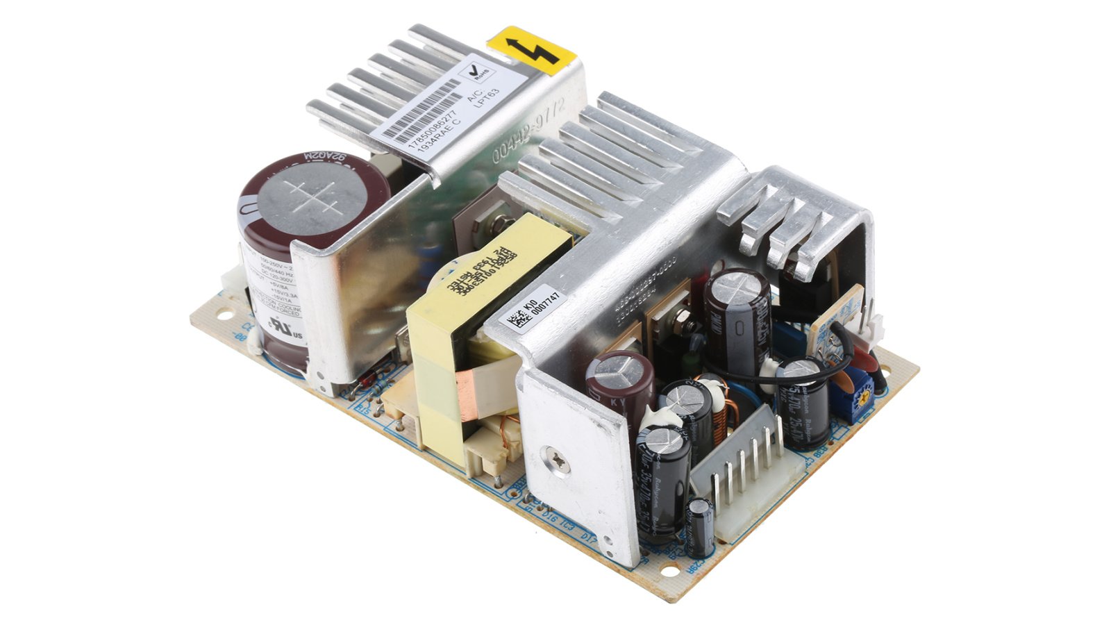
Separate noisy power return paths from analog references and rail supervisors. Route feedback from the load-side sense point where remote sensing is not used, and keep it away from the switching node and transformer drain waveform. Place secondary rectifiers, output capacitors and transformer windings in compact loops. The optocoupler feedback trace belongs in a quiet corridor across the isolation boundary.
Thermal calculations need actual loss estimates for the MOSFET, transformer, rectifiers, bridge, inrush limiter and post-regulators. Open-frame ratings usually assume a particular airflow and ambient temperature. Verify hotspot temperature in the final enclosure, because a module that is comfortable on an open bench may run much hotter beside other equipment.
Validate the Corners, Not Just the Nominal Point
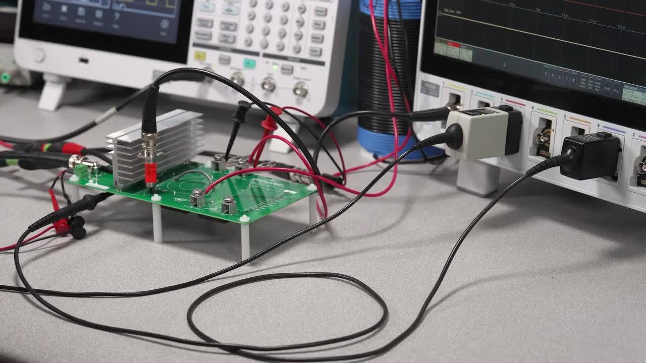
Measure every rail over low, nominal and high line, then repeat at minimum and maximum load on every other rail. This cross-load matrix is the most important test unique to multi-output supplies. Record static accuracy, ripple bandwidth, transient response, startup overshoot, sequencing and shutdown discharge.
Pre-compliance testing should cover conducted and radiated emissions, EFT/burst, surge, ESD where applicable, dielectric withstand, insulation resistance and protective-earth continuity. The applicable standards depend on the finished equipment category and market. Component approvals help, but they do not certify the assembled product.
A Practical Design Review Checklist
Before releasing the module, confirm that each output has a current budget and tolerance over temperature; the feedback rail is justified by the load profile; cross-regulation passes at every load corner; controlled rails have fail-safe logic, discharge and backfeed protection; protection thresholds include tolerance and hysteresis; transformer insulation and PCB spacing match the required safety category; hot components remain within derated limits in the real enclosure; and EMI and immunity results come from representative wiring and loads.
Conclusion
A successful multi-output AC/DC module is designed around rail interactions rather than a list of nominal voltages. The most robust solution usually combines one isolated offline converter, deliberate selection of the feedback rail, local post-regulation for precision outputs, isolated enable control and independent fault supervision where the load risk justifies it.
For OEM projects that need +5 V, +6 V, +9 V or bipolar ±12 V rails in a constrained assembly, SIPURUI can support the discussion with load budgeting, topology selection, mechanical constraints and a verification plan before a custom power supply is committed to tooling.