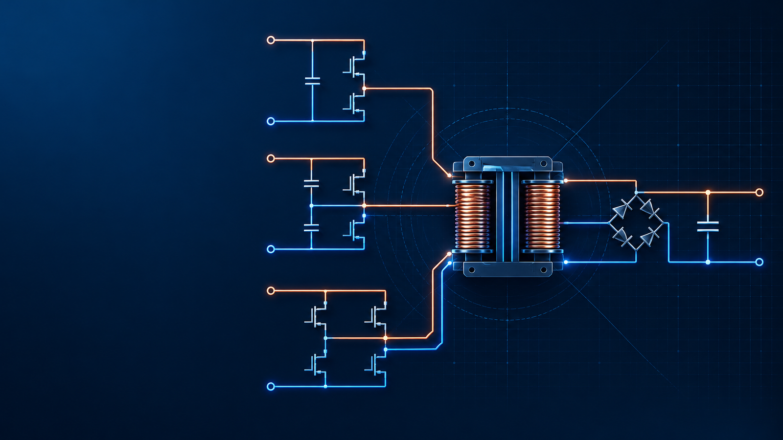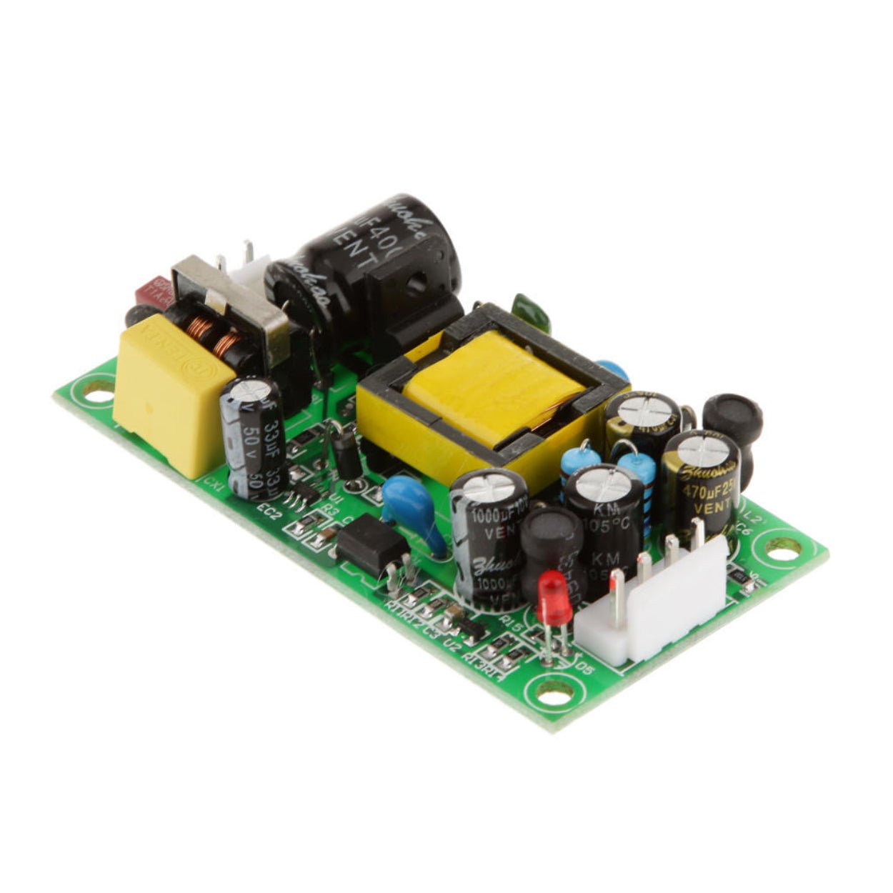
A power supply that runs comfortably at 3 A can still demand 20 A or more for a few milliseconds when it is connected. That short event is enough to trip an upstream adapter, open a fuse, pit a connector, pull down a shared DC bus, or reset nearby controllers. Repeated starts also add electrical and thermal stress to rectifiers, MOSFETs, capacitors, and PCB traces.
A power supply that runs comfortably at 3 A can still demand 20 A or more for a few milliseconds when it is connected. That short event is enough to trip an upstream adapter, open a fuse, pit a connector, pull down a shared DC bus, or reset nearby controllers. Repeated starts also add electrical and thermal stress to rectifiers, MOSFETs, capacitors, and PCB traces.
The usual response is to “add soft start.” That phrase hides two different jobs. The soft-start function inside a regulator controls how the converter builds its output. It does not automatically limit the current that charges a bulk capacitor placed directly across the input. If the wrong problem is treated, a larger soft-start capacitor may slow the output ramp while the damaging input spike remains unchanged.
This guide separates those mechanisms and shows how to choose among an NTC thermistor, a resistor-and-relay pre-charge circuit, a discrete MOSFET stage, or a hot-swap controller. The goal is not the longest possible startup. It is a controlled startup that stays within the source, switch, capacitor, and load limits under both cold-start and hot-restart conditions.
First determine where the surge is coming from
Two charging events are commonly grouped under the same name.
Input bulk-capacitor charging
At connection, a discharged input capacitor initially presents a very low impedance. The peak current is limited mainly by the source impedance, cable and connector resistance, rectifier impedance, capacitor ESR, and any intentional series element. A simplified capacitor relationship is:
I = C × dV/dt
This equation is more useful than treating inrush as a fixed multiple of rated current. A 2,200 µF capacitor charged through a controlled 24 V/s ramp draws about 52.8 mA from the ideal ramp alone. Connect the same capacitor to a stiff 24 V source with only 100 mΩ of total path resistance and the theoretical first instant is 240 A. Parasitics and source collapse reduce the measured peak, but the example shows why capacitance and source impedance matter.
An input limiter must sit in the charging path. Internal PWM soft start cannot control current that flows before the converter begins switching.
Output-capacitor charging and converter startup
Once the controller starts switching, it must charge the output capacitor while supplying any load already connected. If duty cycle or current command rises too quickly, the converter can hit current limit, overshoot, or enter a restart cycle. A controller SS pin normally ramps an internal reference or current command so the output voltage builds gradually. Texas Instruments describes this function as slowly bringing a regulator to its programmed duty cycle and output voltage, which reduces output-side startup current and avoids false current-limit shutdowns.
The practical rule is simple: use the controller’s soft start for converter startup, and add an input-side limiter when the input capacitor or live bus is the source of the surge. Many industrial designs need both.
| What the measurement shows | Likely source | First design action |
|---|---|---|
| A narrow current spike appears immediately at connector contact, before output voltage moves | Input bulk-capacitor charging | Add or redesign the input inrush limiter |
| Current rises after switching begins and follows the output ramp | Output capacitor and load startup | Review SS timing, current limit, and startup load |
| Upstream voltage collapses and recovers repeatedly | Source protection interacting with inrush or converter UVLO | Reduce input inrush and check UVLO hysteresis |
| Cold start passes but immediate restart fails | Hot NTC or insufficient reset/discharge behavior | Test hot restart; move to an active limiter if required |
What each soft-start method can and cannot do

Controller soft start through an SS pin
An external capacitor on the SS pin is inexpensive and should normally be used when the regulator provides the function. The data sheet defines the charging current, threshold, and relationship between capacitance and startup time. Do not select the capacitor from a generic formula copied from another controller.
Longer is not automatically safer. During the ramp, the converter may operate at current limit while a load is already active. A slow ramp can cross a supervisor threshold late, violate sequencing requirements, or cause the controller’s fault timer to expire. In isolated converters, a load that turns on partway through the ramp can pull the output back down and start a power-cycling loop.
Use SS to control output-voltage rise and output-capacitor charging. Then verify startup at minimum input voltage, maximum load, maximum output capacitance, and the coldest expected temperature.
NTC thermistor
An inrush-current-limiting NTC has relatively high resistance when cold. Load current heats it, reducing its resistance for normal operation. TDK identifies three basic selection parameters: rated cold resistance at 25 °C, maximum permissible continuous current, and the maximum capacitance or pulse energy the part can switch.
NTCs remain popular because they need no control circuit. Their weakness is equally clear: after power is removed, a hot device stays at low resistance until it cools. An immediate restart can therefore resemble an unprotected connection. High ambient temperature also lowers initial resistance, while light steady-state load may not heat the device enough to reach the resistance assumed in loss calculations.
Choose an NTC when startup intervals are long, cost and part count dominate, and a hot-restart test confirms the source and fuse can tolerate the residual surge. Do not parallel ordinary NTC inrush limiters to gain current capacity; resistance mismatch causes unequal heating and current sharing.
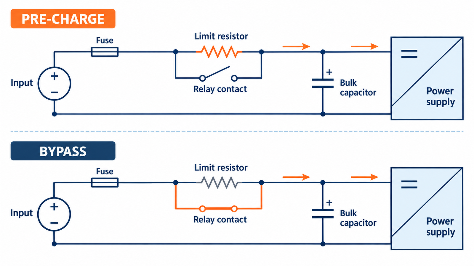
Pre-charge resistor with relay or contactor bypass
This circuit inserts a resistor during capacitor charging and shorts it with a relay after the bus reaches a safe level. Unlike an NTC, the resistor’s initial value does not depend on its previous temperature to the same degree. Once bypassed, steady-state loss is mainly the relay contact resistance.
The initial estimate is R ≥ V / I_LIMIT, but that is only the first line of the calculation. The resistor must also absorb approximately ½CV² for each charge event, with margins for source tolerance, repetition rate, and incomplete discharge. Check the pulse-energy curve, not just the resistor’s continuous wattage.
Bypass based on measured bus voltage where practical. A fixed delay can close too early at low input voltage, high capacitance, or cold temperature. Include a failure analysis for welded contacts, a relay that never closes, and a control supply that is not yet stable. If the relay fails open, the resistor may carry continuous load current and overheat unless a timeout or thermal safeguard removes power.
Discrete MOSFET ramp circuit
A pass MOSFET can produce a compact, silent DC-only limiter. A gate RC network slows turn-on so the downstream capacitor charges more gradually. The attractive schematic can be misleading: while the MOSFET is partially enhanced, it operates in its linear region and simultaneously carries current and drops voltage.
The critical check is safe operating area, not only RDS(on). A MOSFET advertised for a large pulsed drain current may have limited linear-mode capability. Estimate the worst startup trajectory, plot voltage and current against time, and compare it with the data-sheet SOA at the relevant case temperature. Add margin for capacitance tolerance, input surge, gate-threshold spread, and repeated restarts.
A bare RC gate ramp does not guarantee constant current. Load capacitance, gate charge, Miller behavior, and input voltage all change the waveform. For higher energy or wide operating ranges, closed-loop current control is usually easier to qualify.
Hot-swap or eFuse controller
Hot-swap and eFuse devices monitor current and control a pass element during connection. Depending on the part, the MOSFET may be integrated or external. Many industrial-voltage hot-swap controllers drive an external N-channel MOSFET so the designer can select voltage, current, thermal, and SOA capability. Some lower-current devices integrate the MOSFET and sense element.
These controllers can provide a programmed output slew rate, current limit, undervoltage and overvoltage lockout, fault timing, and power-good signaling. Analog Devices’ LTC4216, for example, drives an external MOSFET and uses an adjustable soft-start function with analog current limiting. TI’s LM5069 evaluation platform covers 9–80 V systems and includes an external MOSFET gate driver, programmable fault timer, and power limiting.
The added control is valuable for live backplanes, field-replaceable modules, telecommunications equipment, and DC systems that must restart predictably while warm. It does not remove the SOA calculation. The controller may hold the MOSFET in its linear region during startup or a fault, so timer settings, current limit, and MOSFET thermal impedance must be designed together.

Comparison table for early architecture selection
| Method | Best fit | Hot restart | Normal loss | Main design risk |
|---|---|---|---|---|
| Regulator SS pin | Output ramp control in nearly any converter | Repeatable if controller resets correctly | Negligible | Cannot limit a directly connected input capacitor |
| NTC limiter | Low-cost AC or DC input with infrequent starts | Weak until the NTC cools | Continuous heat and voltage drop | Hot restart and high-ambient performance |
| Resistor plus relay bypass | Medium- to high-energy pre-charge where size is acceptable | Good when control resets correctly | Very low after bypass | Early bypass, welded contacts, or resistor left in circuit |
| Discrete MOSFET ramp | Compact DC equipment with moderate energy | Good if the control circuit resets | Low when fully enhanced | Linear-mode SOA failure during a slow ramp |
| Hot-swap or eFuse controller | Live insertion, frequent restart, tight current limit, or added protection | Excellent when properly configured | Sense and MOSFET conduction loss | Incorrect current/timer settings or inadequate MOSFET SOA |
A practical selection sequence
Start with measurements rather than topology preference.
1. Define the source. Record minimum and maximum input voltage, source current limit, cable impedance, fuse or breaker characteristic, and whether the bus is shared.
2. Quantify stored energy. Include worst-case input capacitance, tolerance, and any downstream capacitance connected through ideal-diode or EMI-filter paths.
3. Specify a current envelope. Set an acceptable peak, pulse width, repetition rate, and maximum bus droop. A single peak-current number is incomplete.
4. Define restart behavior. State the shortest off time and whether hot insertion is allowed. This one requirement often eliminates an NTC.
5. Check startup load. Determine whether motors, controllers, or DC/DC stages are enabled before the pre-charge process finishes.
6. Choose the simplest method that passes every condition. Low-energy, infrequent startup may suit an NTC. Higher energy with low steady loss may favor a bypass relay. Compact or frequently switched DC equipment usually points to an active MOSFET controller.
For AC mains equipment, remember that the capacitor is usually after the bridge rectifier. Component voltage, insulation, fuse coordination, discharge resistors, creepage, and safety approvals become part of the design. Do not transplant a low-voltage DC MOSFET circuit into a rectified-mains input.
Common failures and what they reveal
| Symptom | Probable cause | Corrective direction |
|---|---|---|
| The input spike is unchanged after increasing the SS capacitor | The surge charges an input capacitor before PWM starts | Add an input-path limiter |
| Full-load startup enters hiccup mode | Startup time, current limit, or fault timer is incompatible with the load | Reduce startup load, retune SS, or revise protection timing |
| NTC design passes cold tests and blows fuses after a brief outage | The thermistor is still hot and low resistance | Specify recovery time or use an active/pre-charge solution |
| Pre-charge resistor runs hot in normal operation | Bypass relay did not close or contact path is incorrect | Add bypass confirmation, timeout, and fault shutdown |
| MOSFET fails during a slow startup with no steady-state overload | Linear-mode SOA was exceeded | Shorten the stress interval, reduce current, or select a suitable MOSFET/controller |
| Shared 24 V bus dips when one module connects | Current limit or dI/dt is too high for source impedance | Reduce ramp current and validate bus droop with all loads present |
How to validate the design on the bench
An equipment-level pass/fail test is not enough. Capture the waveform.
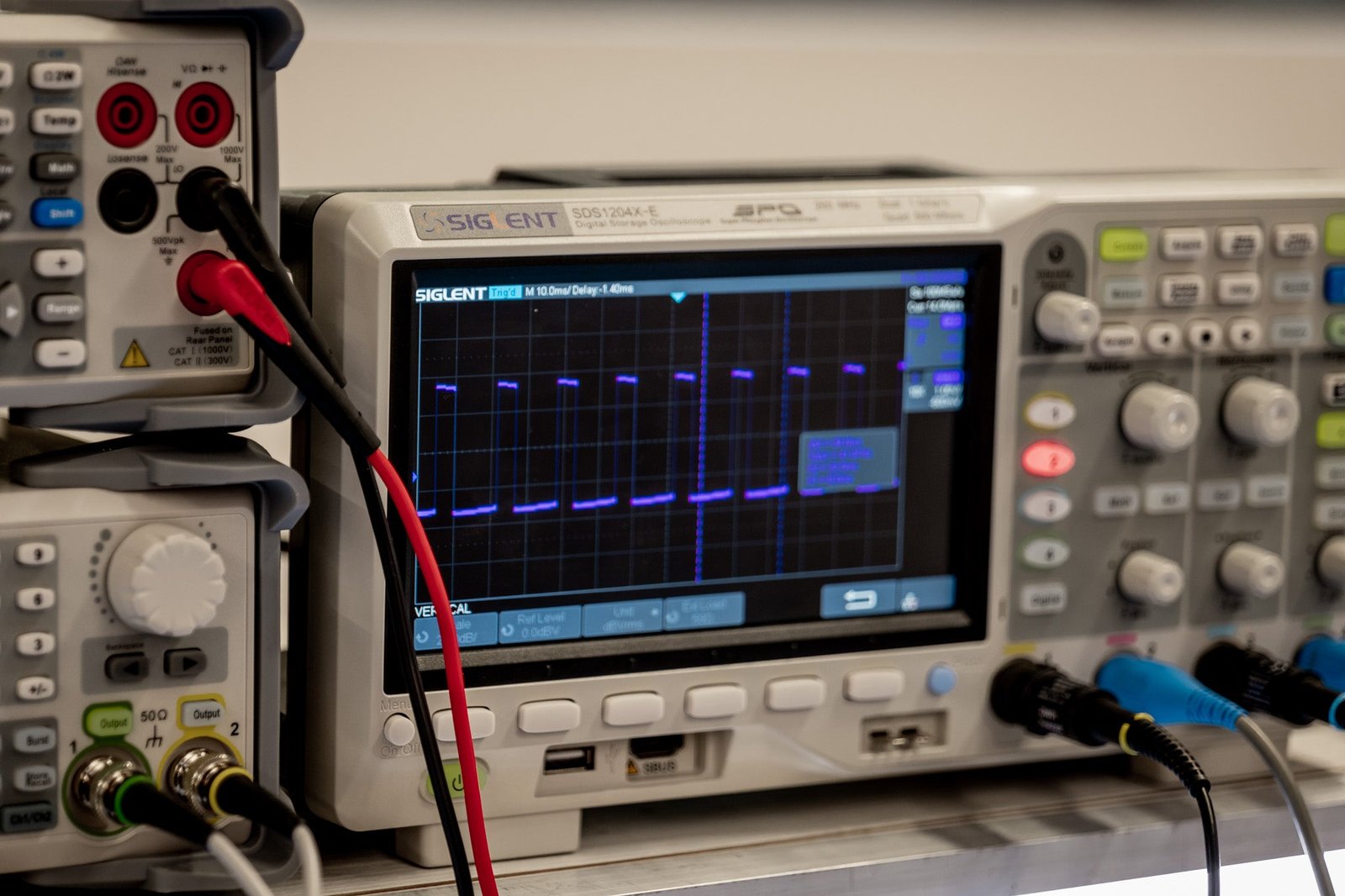
Use a current probe with adequate bandwidth, or a properly rated low-inductance shunt and differential measurement. Measure input current, voltage at the connector, voltage after the limiter, output voltage, and the gate or bypass-control signal. Trigger on the connection event and retain enough pre-trigger time to see what happens before switching begins.
Run at least these conditions:
Minimum and maximum input voltage.
Minimum and maximum specified input and output capacitance.
No load, nominal load, and maximum startup load.
Cold start at the lowest operating temperature.
Immediate hot restart at the highest operating temperature.
Repetitive starts at the shortest allowed interval.
Current-limited or weak upstream source.
A controlled start into a short, if the protection concept claims to handle it.
Record peak current, pulse duration, capacitor voltage ramp, bus droop, output overshoot, and component temperature. For a MOSFET solution, convert the captured VDS and ID waveforms into an energy and SOA check. For a resistor, compare each pulse and the start repetition rate with the manufacturer’s pulse-overload data. For a relay, inspect the voltage difference at contact closure; a large step means bypass occurred too early.
Buyer and design-review checklist
When a switching power supply vendor quotes “soft start,” ask what the specification actually covers. Useful questions include:
Is the stated value an input inrush limit, an output-voltage rise time, or both?
At what input voltage, source impedance, temperature, and capacitor value was it measured?
Is the inrush specification a maximum or only a typical waveform?
Does the unit behave differently on an immediate restart?
Can several units start from the same AC branch or DC bus without nuisance tripping?
Does the design use an NTC, a bypass circuit, or active current limiting?
What are the minimum off time, startup load limit, and recommended upstream fuse characteristics?
These details matter more than a generic “soft-start included” statement. They also make incoming inspection easier because the buyer can reproduce the vendor’s test conditions.
Final recommendation
Treat soft start as two coordinated functions. The regulator’s SS network controls the converter and output-voltage ramp. The input limiter manages the energy needed to charge bulk capacitance from the source. Configure both when both mechanisms are present.
An NTC is a sensible low-cost choice when starts are infrequent and hot restart is not demanding. A resistor with relay bypass handles larger energy with low running loss. A discrete MOSFET saves space but requires a serious linear-mode SOA review. For frequent connection, tight current control, or fault reporting, a hot-swap or eFuse controller is usually the more predictable engineering choice.
SIPURUI can support power-supply selection discussions with input range, load profile, installation environment, and restart requirements. The most useful request is not simply “reduce inrush.” Provide the bus voltage, total capacitance, allowed peak current, minimum off time, and startup load so the proposed solution can be checked against the real operating envelope.