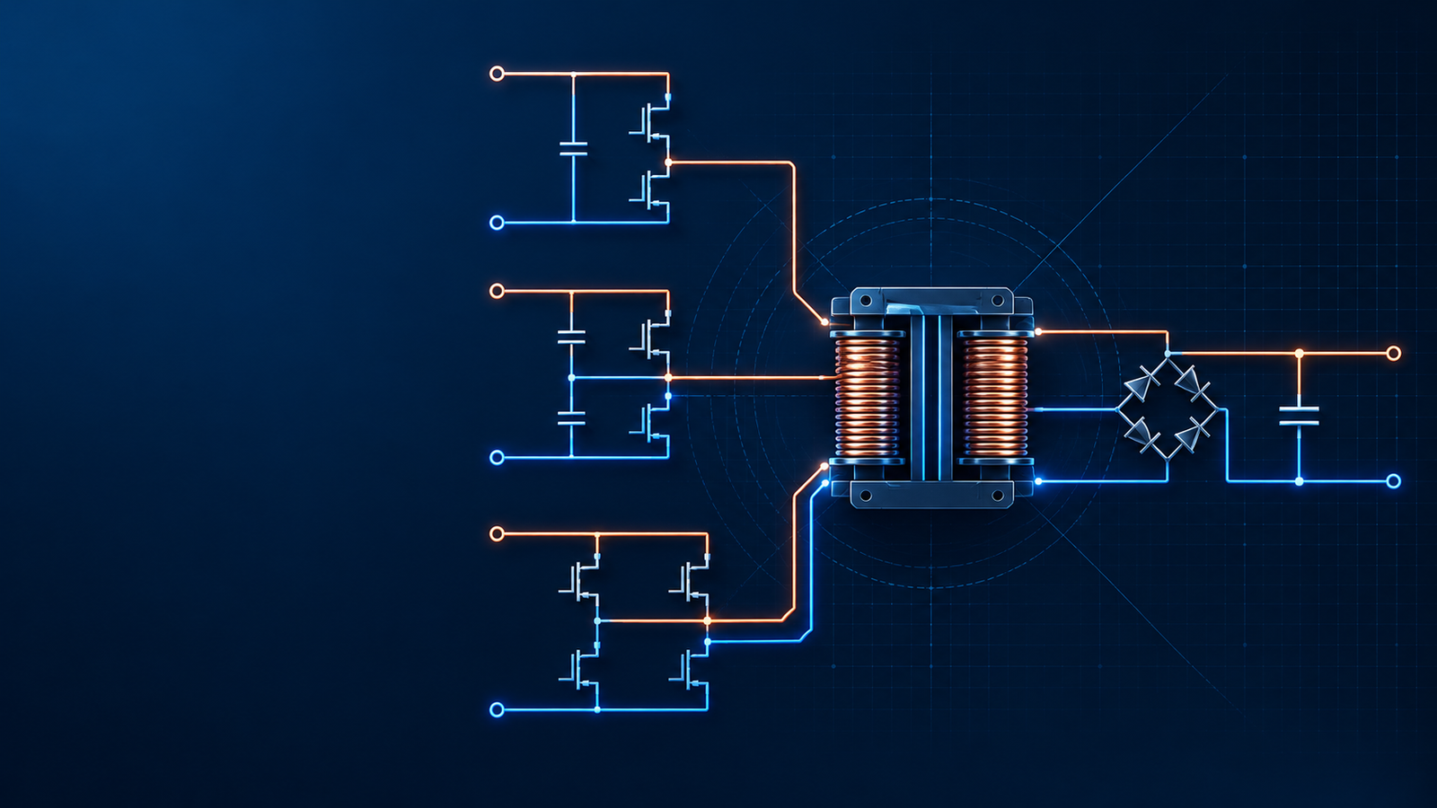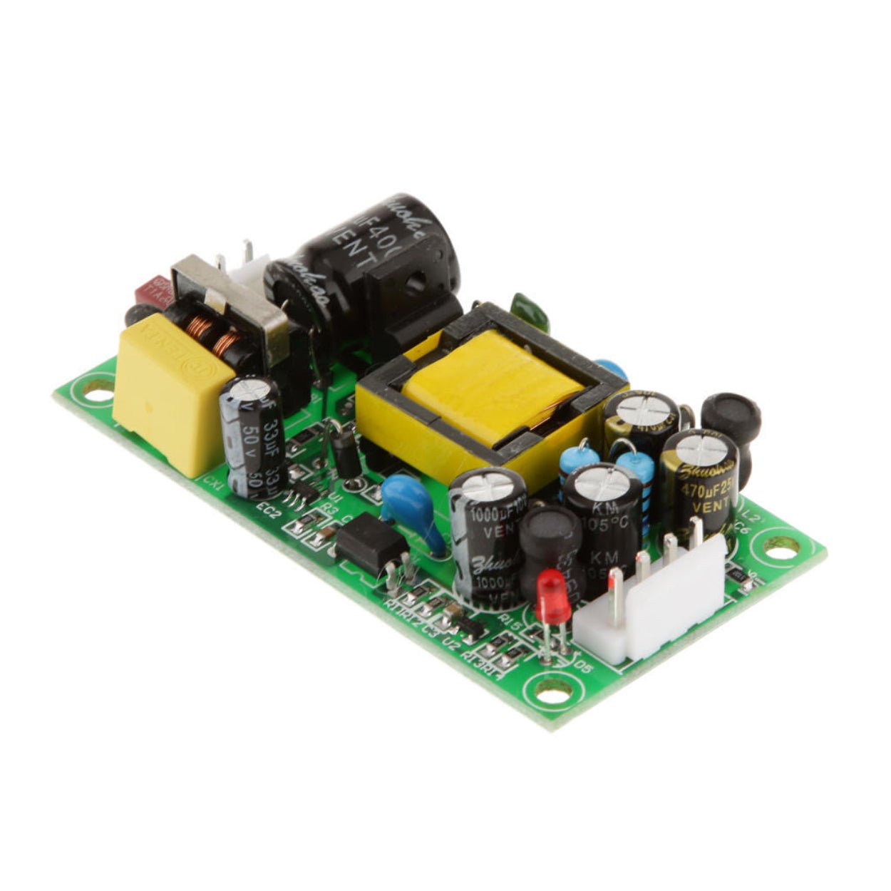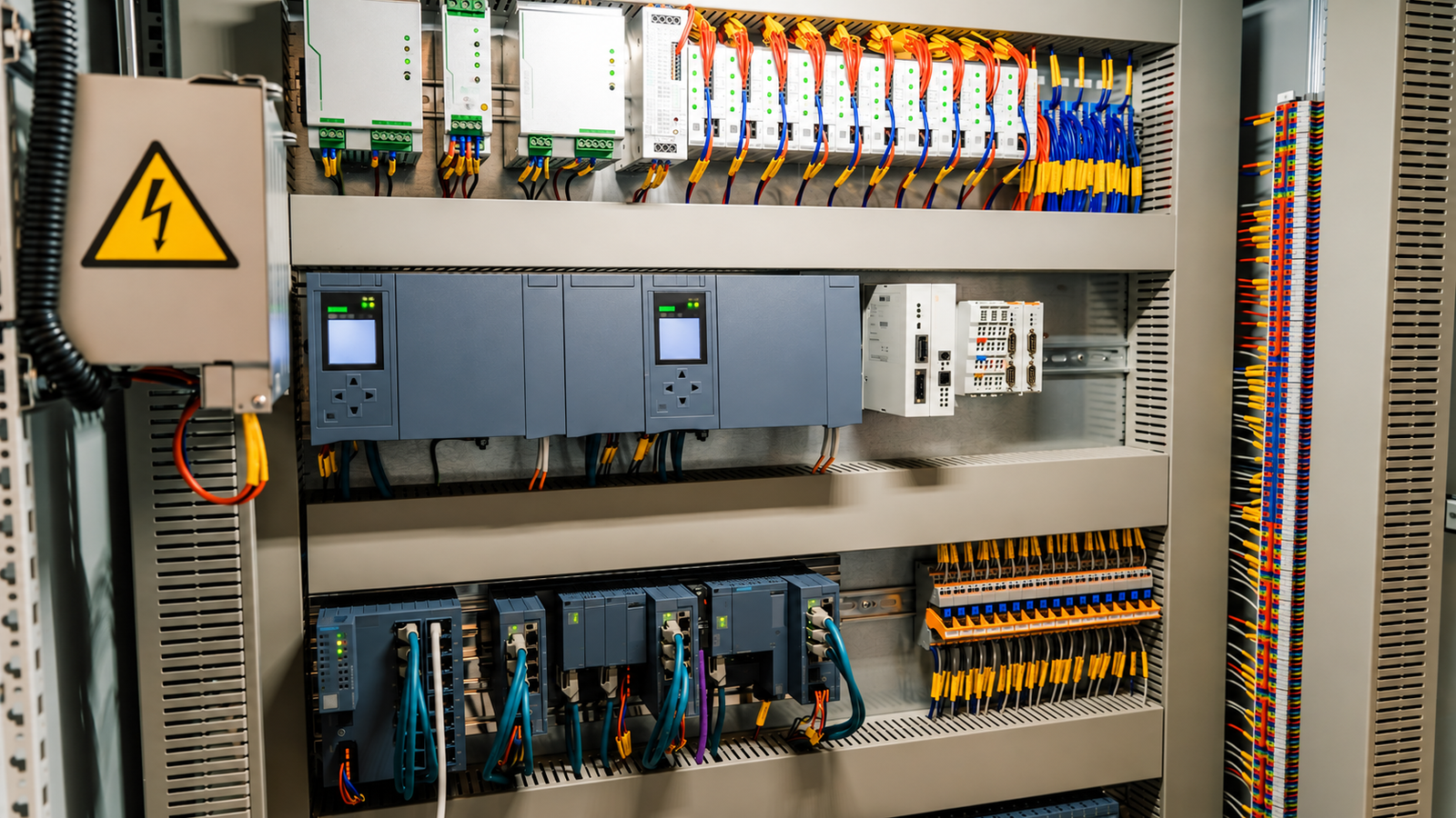
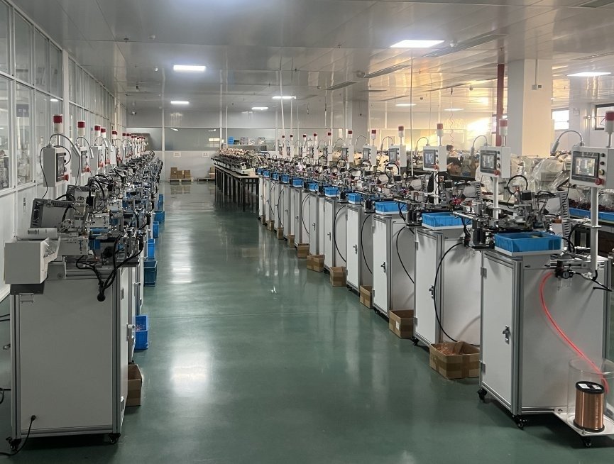
When an isolated switching power supply misses its efficiency target or fails EMC testing, the first suspects are usually the PCB layout, snubber, MOSFET, rectifier, or control loop. That is sensible, but incomplete. The transformer may meet its turns ratio and inductance specifications and still impose a hard limit on the finished power supply.
Overview
When an isolated switching power supply misses its efficiency target or fails EMC testing, the first suspects are usually the PCB layout, snubber, MOSFET, rectifier, or control loop. That is sensible, but incomplete. The transformer may meet its turns ratio and inductance specifications and still impose a hard limit on the finished power supply.
Winding construction changes leakage inductance, interwinding capacitance, AC copper loss, insulation stress, thermal paths, and coupling between the power and auxiliary windings. Those properties affect switch-node ringing, common-mode current, rectifier stress, cross-regulation, no-load behavior, temperature rise, and safety margins.
So, does the winding process directly determine performance? It determines a substantial part of the achievable performance, especially in compact high-frequency converters. It does not replace sound topology selection, magnetics calculations, PCB layout, control design, component selection, or thermal engineering. A good transformer cannot rescue a poor converter, but an inconsistent winding process can prevent a good design from reaching production.
Why winding construction matters at switching frequency
A high-frequency transformer is not an ideal turns-ratio device. Each real winding has resistance, leakage inductance, distributed capacitance, and a physical relationship to every other winding. As switching edges become faster, these parasitic elements carry more energy and provide new paths for noise.
Leakage inductance stores energy that is not transferred through the intended magnetic coupling. When the primary switch turns off, that energy can appear as a drain-voltage spike and ringing. A clamp or snubber can control the spike, but it must dissipate or recycle the energy. Lower leakage inductance can therefore reduce device stress and snubber loss.
Interwinding capacitance creates another path. A fast primary-side voltage transition drives displacement current through the capacitance between primary and secondary. That current contributes to common-mode emissions. Texas Instruments notes that reducing leakage inductance through tighter coupling can increase interwinding capacitance, so the winding should be optimized for the converter and its EMI path rather than for one minimum number alone.
AC winding resistance also differs from DC resistance. Skin and proximity effects crowd current into part of the conductor at high frequency. Layer count, wire diameter, strand arrangement, foil thickness, and the field generated by adjacent windings all change the loss. A winding that looks acceptable on a DC resistance check may run hot at full load.
| Winding-dependent property | What changes it | Typical system consequence |
|---|---|---|
| Leakage inductance | Winding separation, layer count, interleaving, incomplete layers, lead routing | Switch and diode spikes, ringing, snubber loss, poorer cross-regulation |
| Interwinding capacitance | Overlap area, spacing, insulation system, electrostatic shields, layer arrangement | Common-mode current, conducted and radiated EMI, touch-current trade-offs |
| AC resistance | Conductor size, strand layout, foil thickness, proximity field, winding fill | Lower efficiency, local heating, reduced power density |
| Coupling to auxiliary windings | Position, polarity, loading, lead routing | Biased sensing, poor housekeeping supply regulation, startup or restart problems |
| Insulation integrity | Tape margins, barriers, sleeving, creepage paths, workmanship | Hipot failure, leakage current, reduced lifetime, safety risk |
Winding order is an electrical design choice
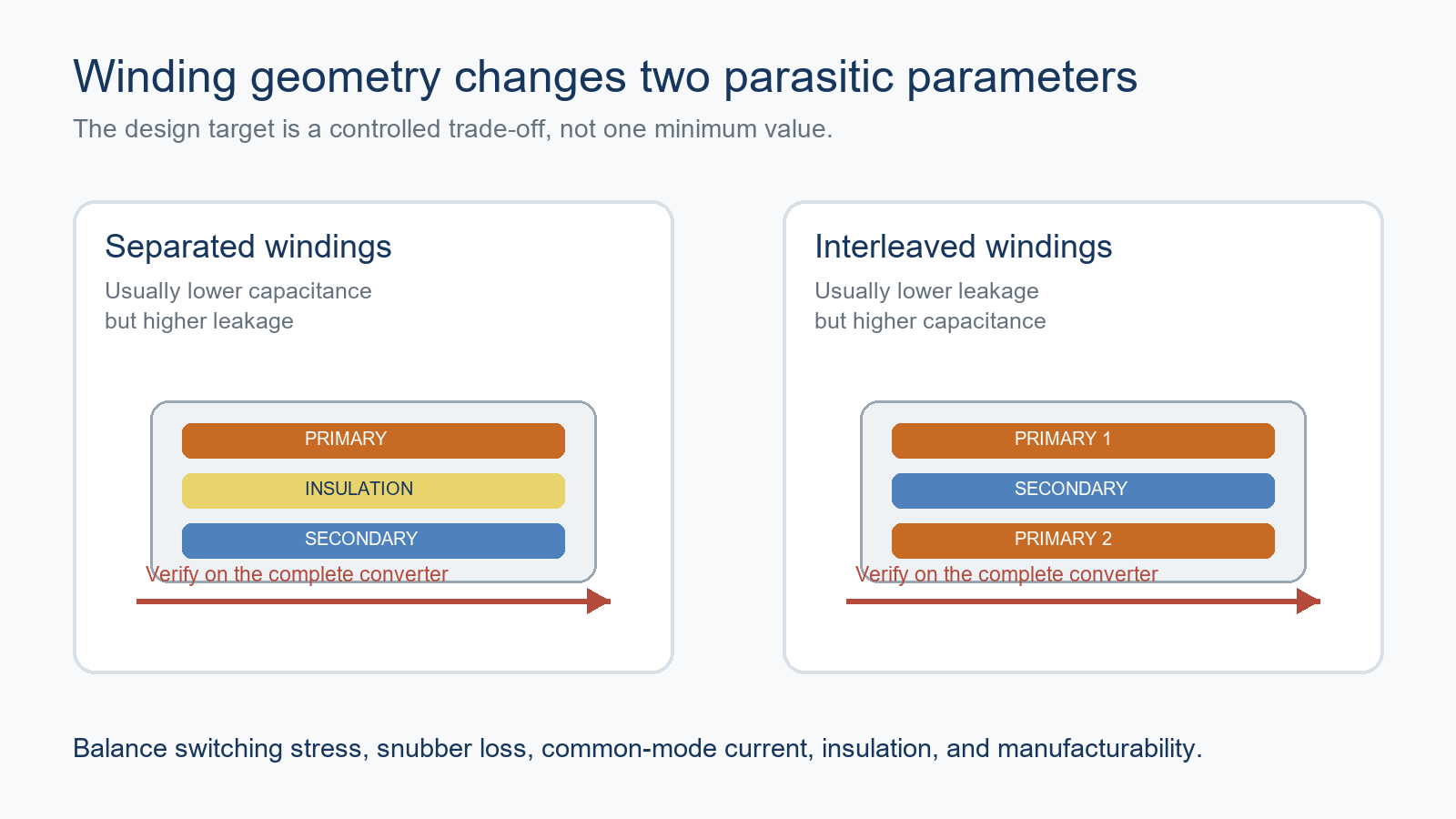
In many flyback and forward transformers, splitting the primary and placing the secondary between the two primary sections improves magnetic coupling. The familiar primary-secondary-primary arrangement often lowers leakage inductance because the windings share more magnetic field.
That improvement has a cost. Increased overlap can raise primary-to-secondary capacitance. In equipment with tight common-mode EMI or leakage-current limits, a fully interleaved structure may perform worse than a carefully separated or shielded construction. The right answer depends on switch-node dv/dt, power level, safety insulation, Y-capacitor allowance, enclosure grounding, and the current return path through the final product.
The auxiliary winding also deserves deliberate placement. In a flyback converter, its waveform is used for controller bias and sometimes for primary-side regulation or protection. Coupling it closely to the regulated secondary can improve tracking, while placement near a noisy primary layer may add ringing to the sampled voltage. The correct position depends on which voltage the auxiliary winding must represent.

Neat winding is useful, but “as tight as possible” is not a specification
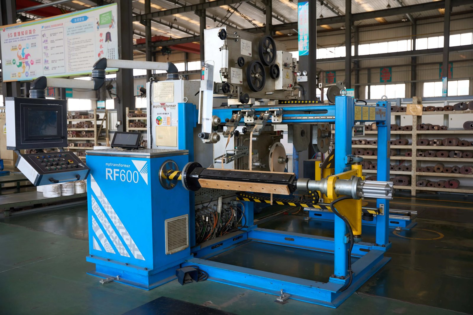
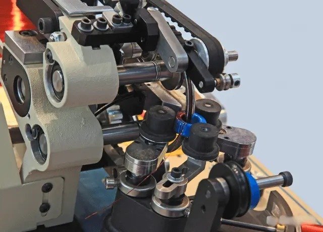
Orderly turns help fill a layer consistently and make the distance between windings repeatable. Random crossing, bunching, or gaps can change both leakage inductance and capacitance from unit to unit. It can also concentrate the electric field and create local hot spots.
Excessive tension is not an improvement. It can damage enamel, deform a bobbin, displace tape, or pull a lead against a sharp edge. Loose turns may move during varnish impregnation or operation, increasing audible noise and changing the geometry. Production documentation should therefore define wire tension, traverse pitch, layer fill, tape overlap, margins, and acceptable lead routing. “Wind neatly” is not a controllable instruction.
For high-current windings, several smaller conductors or litz wire may reduce AC loss, but only if current sharing remains reasonably even. Unequal strand length, poor termination, or uncontrolled bunching can defeat the purpose. Foil windings have their own constraints: termination resistance, edge insulation, fringing fields, and circulating currents must be managed.
Insulation controls safety and parasitic behavior
Primary-to-secondary insulation must satisfy the applicable safety standard and working voltage. Tape material, thickness, number of layers, margin tape, sleeving, triple-insulated wire, bobbin geometry, and creepage and clearance distances form one insulation system. Changing one item can alter both safety performance and electrical behavior.
Adding insulation indiscriminately can increase winding separation and leakage inductance. Reducing insulation to improve coupling is unacceptable when it compromises reinforced or basic insulation requirements. The practical task is to meet the required insulation system while controlling the geometry tightly enough that leakage and capacitance remain inside their production limits.
Electrostatic shields can reduce capacitive noise transfer when they are placed and connected correctly. A copper shield must not form a shorted turn. Its connection point should return noise to the intended quiet node without creating a new loop. Shield design needs verification on the actual converter because a shield can reduce one emission band while adding capacitance or loss elsewhere.
Leads, terminations, core assembly, and impregnation
The winding does not end at the last turn. Long high-dv/dt leads add loop area and can behave like small antennas. Primary and secondary leads that cross unnecessarily may increase capacitive coupling. Production drawings should show start and finish pins, routing paths, sleeving, bend radius, and where the leads are anchored.
Core assembly is equally important. A displaced or inconsistent air gap changes magnetizing inductance and peak flux. Contamination or uneven mating surfaces can produce unexpected gap variation. Clamp force, adhesive, tape, and cure conditions must keep the core stable through vibration and thermal cycling without cracking the ferrite.
Impregnation or varnishing can secure the winding, reduce movement, and improve resistance to moisture and vibration. It may also affect thermal transfer. The process has to be controlled: viscosity, vacuum or soak conditions, drainage, cure temperature, and cure time all influence the result. Excess varnish can complicate assembly; incomplete cure or poor penetration can leave the original mechanical problem in place.
Symptoms that should trigger a transformer investigation
Transformer construction should move up the diagnostic list when a problem follows transformer lots, changes with clamp pressure, or remains after reasonable PCB and component checks. Compare suspect units with a known-good transformer using the same board and test conditions.
| Symptom | Transformer-related checks | Other checks that still matter |
|---|---|---|
| Drain spike or strong ringing | Leakage inductance, interleaving, lead length, core gap | Clamp values, probe technique, switch-node layout |
| Conducted or radiated EMI failure | Interwinding capacitance, shield connection, primary lead routing | Input filter layout, Y capacitor, chassis and cable paths |
| Transformer runs hot | AC resistance, strand sharing, proximity loss, core gap, flux density | Core material, switching frequency, waveform, airflow |
| Poor auxiliary regulation or restart | Auxiliary position, polarity, coupling, lead routing | Controller thresholds, bias rectifier and capacitor |
| Intermittent hipot failure | Tape margins, sleeving, damaged enamel, pin spacing, contamination | Test fixture, humidity conditioning, PCB creepage |
| Batch-to-batch efficiency spread | Layer fill, tension, termination resistance, gap consistency | Semiconductor variation, soldering, measurement repeatability |
Use measurement methods that reveal construction differences. Record magnetizing inductance and leakage inductance with a defined test frequency and winding condition. Measure winding resistance, turns ratio, polarity, interwinding capacitance where relevant, and hipot or insulation resistance under the approved safety procedure. On the powered converter, compare switching waveforms, clamp dissipation, common-mode current, efficiency, and thermal images.
What to specify for production and sourcing
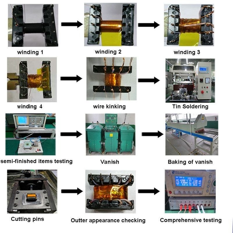
A transformer drawing that lists only core, turns, wire gauge, and inductance leaves too much to interpretation. The approved construction should include a layer-by-layer winding table and photographs or diagrams showing the physical build.
| Control item | What the specification should define | Useful verification |
|---|---|---|
| Winding sequence | Layer order, direction, start and finish pins, split windings | First-article teardown and polarity test |
| Conductor placement | Turns per layer, tension range, strand or foil arrangement | In-process inspection, sectioned samples |
| Insulation system | Materials, tape width and overlap, margins, sleeving, barrier details | Hipot, insulation resistance, material traceability |
| Shielding | Material, coverage, gap, termination pin and connection | Continuity check and converter EMI test |
| Core and gap | Core grade, gap method and tolerance, mating and retention | Inductance, gap inspection, mechanical check |
| Electrical limits | Magnetizing inductance, leakage inductance, DCR, capacitance where needed | Incoming inspection with defined fixtures and frequencies |
| Environmental process | Impregnation material, cure profile, cleanliness requirements | Weight/process records, cure checks, environmental sampling |
For purchasing teams, a golden sample is valuable only when it is tied to controlled documents and measurable acceptance limits. Ask the transformer supplier how winding tension, tape placement, air gap, terminations, and impregnation are controlled. For critical programs, approve a construction record and require change notification before materials, equipment, or winding sequence are altered.
A balanced engineering conclusion
Transformer winding process does not single-handedly determine every switching power supply result. It does set several parasitic, thermal, safety, and consistency limits that the rest of the circuit must live with. This is why a converter can look correct in simulation yet show excessive ringing, EMI, heat, or lot variation in production.
The most reliable approach is co-design. Set transformer leakage, capacitance, loss, insulation, and temperature targets alongside the switching stage, PCB layout, clamp, filter, control loop, and enclosure. Then freeze the construction, validate it on the real converter, and monitor the process with incoming and in-process checks.
For OEM and industrial power projects, SIPURUI can review the power supply operating conditions, transformer construction requirements, EMC constraints, and production test plan as one system rather than treating the transformer as a catalog line item.