Few moments are more frustrating for a power electronics engineer than seeing a carefully designed power supply fail EMC testing.
Overview
Why Do So Many Switching Power Supplies Fail EMI Testing?
Few moments are more frustrating for a power electronics engineer than seeing a carefully designed power supply fail EMC testing. The unit may achieve excellent efficiency, pass thermal evaluations, and demonstrate long-term reliability, yet still exceed conducted or radiated emission limits during certification. When this happens, project timelines are delayed, redesign costs increase, and product launches can be pushed back by weeks or even months.
The reality is that EMI has become increasingly difficult to control as modern power supplies continue to evolve. Industrial equipment is becoming smaller, switching frequencies are increasing, and customers expect higher power density than ever before. Whether the application involves a DIN rail power supply inside an industrial control cabinet, an enclosed switching power supply for factory automation equipment, an industrial AC/DC power supply for communication systems, or an LED power supply operating in a commercial lighting installation, electromagnetic interference remains one of the most significant engineering challenges.
The good news is that EMI rarely appears without a reason. In most cases, excessive emissions can be traced back to identifiable design decisions involving switching devices, transformers, PCB layout, grounding structures, or cable routing. Understanding where the noise originates is the first step toward eliminating it.
What Is Actually Generating EMI Inside a Switching Power Supply?
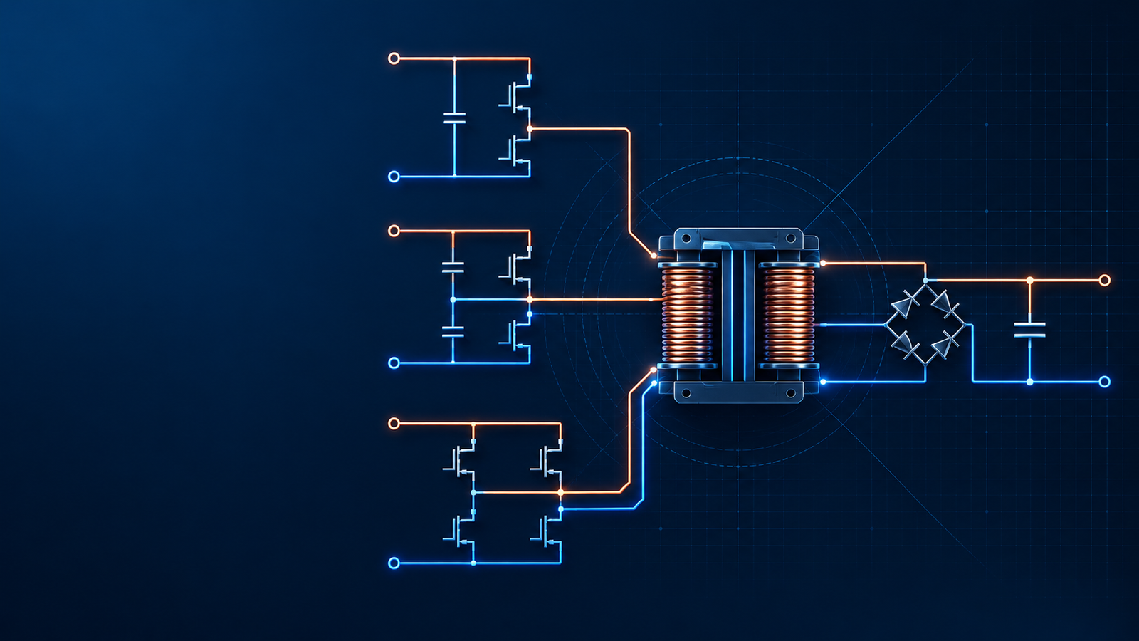
Every switching power supply operates by rapidly turning semiconductor devices on and off. During these transitions, voltage and current can change at extremely high rates. These rapid changes create electromagnetic energy that spreads throughout the circuit and eventually finds a path into cables, metal structures, or nearby electronic equipment.
The most significant EMI sources are usually not difficult to identify. Power MOSFETs, PFC stages, high-frequency transformers, synchronous rectifiers, and switching nodes all generate substantial noise energy. However, the real challenge lies in the interaction between these components and the PCB layout surrounding them.
Many engineers assume that EMI originates exclusively from switching devices. In reality, parasitic inductance and capacitance often amplify the problem. A transformer winding may couple noise into adjacent circuits. A large switching-node copper area may behave like an antenna. A poorly positioned heatsink can become an unexpected radiating structure.
EMI is generally divided into two categories. Conducted EMI travels through power cables and signal wiring, while radiated EMI propagates through space as electromagnetic waves. Although the mechanisms differ, both forms often originate from the same switching events occurring inside the power supply.

Why Is EMI More Critical in Industrial Applications?
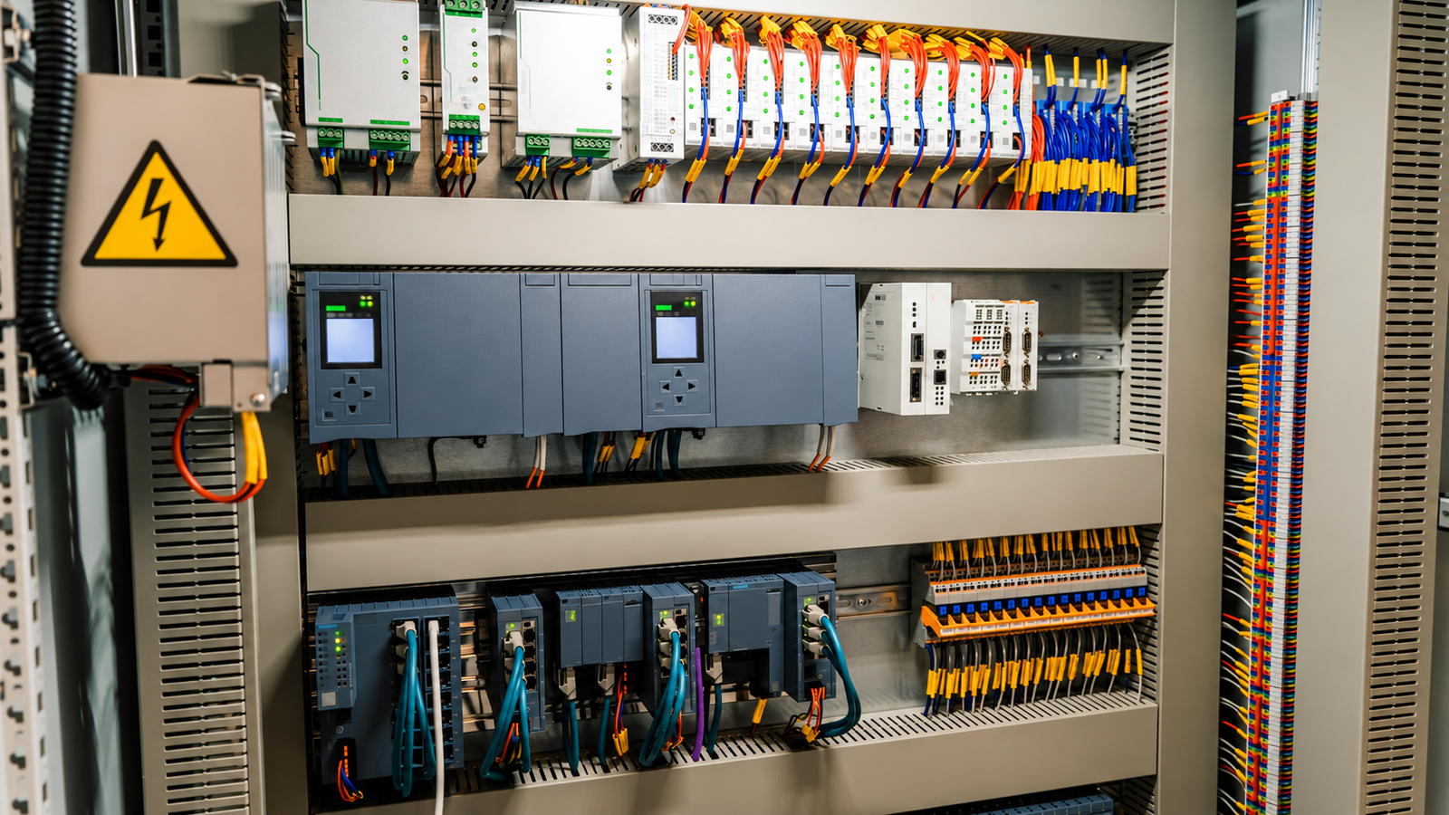
Industrial power supplies operate in environments that are far more demanding than consumer electronics. A modern control cabinet may contain programmable logic controllers, servo drives, motor inverters, Ethernet switches, sensors, and communication modules all installed within a confined space.
Under these conditions, even relatively small amounts of electromagnetic interference can create unexpected problems. Communication networks may experience data corruption. Analog sensors may produce unstable readings. Servo systems may become susceptible to control disturbances. In severe cases, entire production lines can suffer reduced reliability.
This is one reason why EMC compliance has become a key design objective for industrial power supply manufacturers. Companies developing DIN rail power supplies, enclosed power supplies, and industrial AC/DC converters must ensure their products meet increasingly stringent standards while maintaining high efficiency and compact dimensions.

What Can EMI Frequency Tell You About the Root Cause?
One of the most effective troubleshooting methods is to examine the frequency range where emissions exceed regulatory limits. Different frequency bands often point directly toward specific circuit elements.
Table 1. EMI Frequency Range and Typical Noise Sources
| Frequency Range | Typical Noise Source | Common Solution |
|---|---|---|
| Below 1 MHz | Differential-mode noise | Increase X capacitor value |
| 1-5 MHz | Mixed differential and common-mode noise | Optimize input EMI filter |
| 5-10 MHz | Common-mode noise | Improve common-mode choke |
| 10-25 MHz | Grounding and return path issues | Improve grounding structure |
| 25-30 MHz | Transformer coupling and PCB parasitics | Add shielding and optimize layout |
| 30-50 MHz | MOSFET switching transitions | Increase gate resistance and add snubbers |
| 100-200 MHz | Diode reverse recovery noise | Add ferrite beads and optimize rectifiers |
For example, when emissions rise sharply below 1 MHz, differential-mode noise is frequently responsible. Increasing the X capacitor or improving differential-mode filtering often produces measurable improvements. On the other hand, failures in the 5 MHz to 10 MHz range are more commonly associated with common-mode noise and transformer coupling mechanisms.
Engineers who understand these relationships can often reduce troubleshooting time dramatically.
Why PCB Layout Matters More Than Most EMI Filters
Many engineers begin solving EMI problems by adding larger filters. While filters certainly play an important role, they are often compensating for problems that originated in the PCB layout.
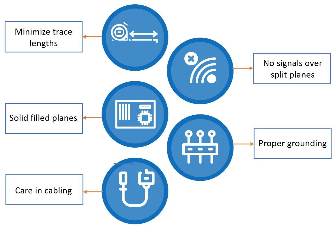
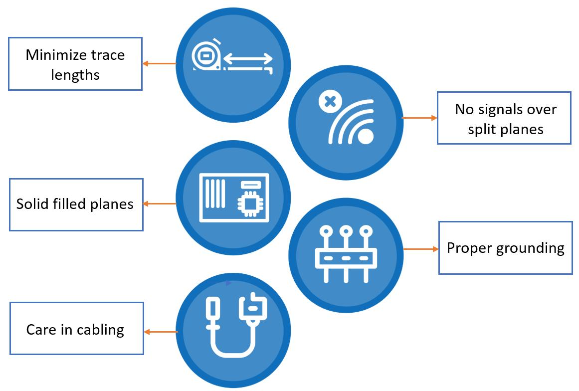
One of the most important principles in EMC design is minimizing high-current loop area. Every switching power supply contains several critical loops, including the primary switching loop, the secondary rectification loop, and the PFC current loop. When these loops occupy excessive PCB area, they effectively become antennas that radiate electromagnetic energy.
Reducing loop dimensions often provides greater EMI improvement than adding additional filtering components. Keeping switching devices close to transformers, placing input capacitors adjacent to MOSFETs, and maintaining compact return-current paths can significantly lower both conducted and radiated emissions.
Another common mistake involves oversized switching-node copper areas. Designers sometimes enlarge these areas to improve thermal performance, but doing so may unintentionally increase radiated noise. Finding the proper balance between thermal management and EMC performance is essential.
Grounding strategy is equally important. A poorly designed return path can transform a relatively quiet circuit into a major EMI source. Proper grounding reduces impedance, limits noise propagation, and improves overall EMC performance.
Which EMI Reduction Techniques Deliver the Greatest Impact?
Although every design is different, experienced engineers tend to focus on several high-impact improvements before making more complex changes.
The first area of attention is transformer design. Since the transformer serves as a coupling path between primary and secondary circuits, it plays a critical role in common-mode noise generation. Copper foil shielding, shield windings, optimized winding arrangements, and improved insulation spacing can all contribute to lower emissions.
MOSFET switching behavior represents another major opportunity for improvement. Many EMI problems in the 30 MHz to 50 MHz range are caused by excessively fast switching transitions. Increasing the gate resistor slightly can reduce dv/dt and significantly lower emission levels. Properly tuned RC snubbers and RCD clamp networks can further suppress ringing without severely impacting efficiency.
Rectifier circuits also deserve attention. Reverse recovery current from fast diodes often generates high-frequency noise extending well beyond 100 MHz. Ferrite beads placed near rectifiers are frequently effective at reducing this type of emission.
Even seemingly minor design details can produce measurable improvements. Moving noisy components away from enclosure edges, increasing spacing between transformers and heatsinks, and improving cable routing can all contribute to EMC compliance.
How Do EMI Challenges Differ Between Power Supply Types?
Not all switching power supplies face the same EMI challenges. Application environments play a major role in determining which suppression techniques are most effective.
Table 2. Common EMI Challenges Across Different Power Supply Types
| Power Supply Type | Typical EMI Challenge |
|---|---|
| DIN Rail Power Supply | Common-mode noise within control cabinets |
| Enclosed Switching Power Supply | High-power switching-node radiation |
| Industrial Power Supply | Strict EMC certification requirements |
| LED Power Supply | Long cable radiated emissions |
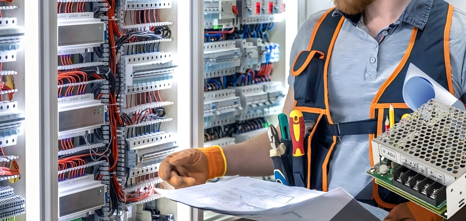
DIN rail power supplies are commonly installed inside automation cabinets alongside PLCs, relays, communication modules, and motor drives. In these environments, common-mode noise can easily couple into adjacent systems through shared grounding structures.
Enclosed switching power supplies often operate at higher power levels, which increases switching currents and makes layout optimization particularly important.
LED power supplies face a different challenge. Output cables can extend several meters from the power supply to the lighting fixture. These long conductors may function as antennas, increasing radiated emissions and creating additional compliance difficulties.
Industrial AC/DC power supplies typically encounter the most demanding EMC requirements because they are expected to operate reliably in electrically noisy environments.
Which Components Are Most Effective for EMI Suppression?
Selecting the correct suppression components is often more important than simply increasing component quantity.
Table 3. Common EMI Suppression Components and Their Functions
| Component | Primary Function |
|---|---|
| X Capacitor | Differential-mode noise suppression |
| Y Capacitor | Common-mode noise suppression |
| Common-Mode Choke | High-frequency filtering |
| Ferrite Bead | High-frequency attenuation |
| RC Snubber | Ringing reduction |
| RCD Clamp | Voltage spike suppression |
Each component targets a specific type of interference. Increasing X capacitor values may improve low-frequency conducted emissions, but it will do little to address high-frequency ringing from a MOSFET. Likewise, ferrite beads can be extremely effective at suppressing high-frequency noise while having minimal influence on lower-frequency emissions.
Successful EMI reduction therefore depends on understanding the actual source of interference rather than applying generic fixes.
A Real-World Example: Solving a 40 MHz EMI Failure
Consider a 240W enclosed switching power supply that passes conducted emissions below 20 MHz but exceeds limits around 40 MHz.
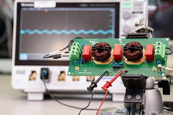
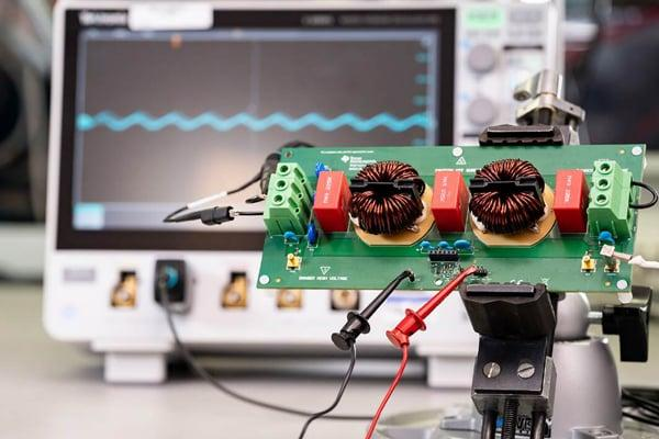
Initial investigation reveals excessive ringing at the drain of the primary MOSFET. Oscilloscope measurements show significant overshoot during switching transitions. Further analysis identifies parasitic inductance in the switching loop combined with aggressive gate drive characteristics.
Instead of redesigning the entire converter, engineers implement three targeted improvements. First, the gate resistor value is increased slightly to slow switching transitions. Second, an optimized RC snubber is added across the switching node. Third, the PCB layout is revised to reduce loop inductance around the MOSFET and transformer.
Following these modifications, emissions around 40 MHz drop substantially and the power supply passes compliance testing without major efficiency penalties.
This example illustrates a key lesson in EMC engineering: understanding the root cause is far more effective than adding random filtering components.
How SIPURUI Designs Power Supplies for EMC Compliance
At SIPURUI, EMC performance is considered throughout the product development process rather than being treated as a final-stage correction. Transformer structures are optimized to reduce common-mode coupling, switching transitions are carefully controlled to balance efficiency and emissions, and PCB layouts are developed with current-loop minimization as a primary objective.
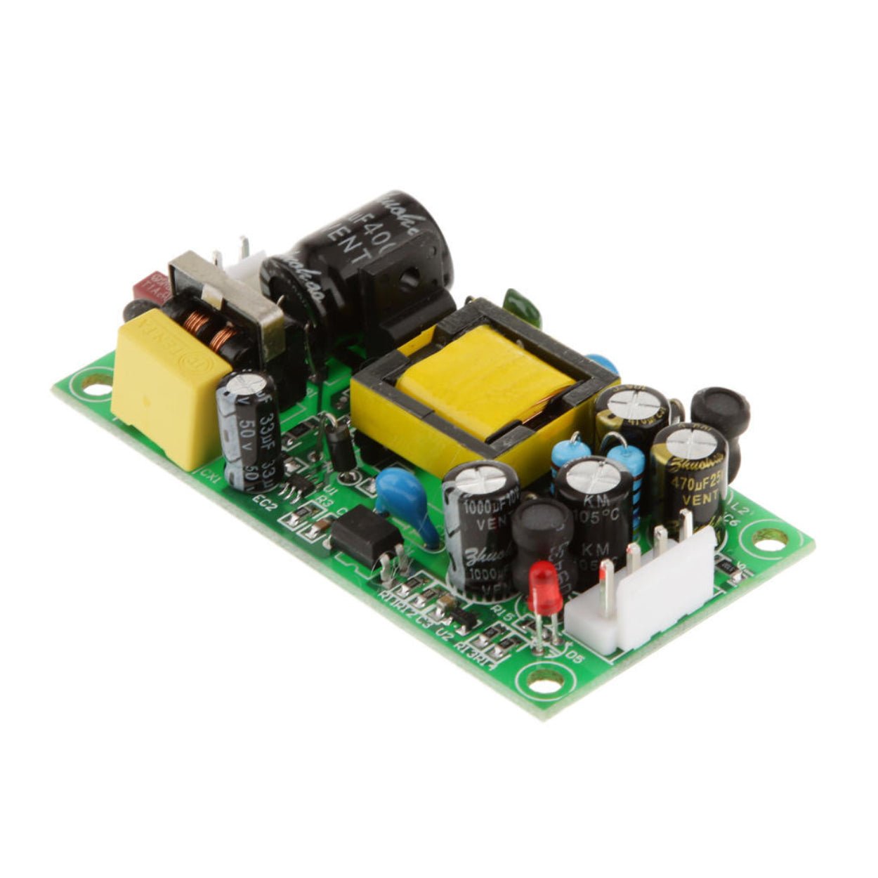
Particular attention is given to products such as DIN rail power supplies, industrial AC/DC converters, enclosed switching power supplies, and LED power supplies, where EMC performance directly affects long-term system reliability.
By integrating EMI suppression into the design process from the beginning, manufacturers can reduce certification risk, shorten development cycles, and deliver more reliable products to industrial customers.
Conclusion
Why do switching power supplies fail EMI testing? In most cases, the answer is not a single component or isolated design flaw. EMI is typically the result of multiple interacting factors, including switching transitions, transformer coupling, PCB layout decisions, grounding structures, and cable routing.
Engineers who understand how noise behaves across different frequency ranges gain a significant advantage during troubleshooting. Rather than relying on trial and error, they can identify likely noise sources, apply targeted corrective actions, and achieve compliance more efficiently.
Whether you are developing a DIN rail power supply, an enclosed switching power supply, an industrial AC/DC converter, or an LED power supply, the principles remain the same. Control current loops, optimize switching behavior, reduce parasitic coupling, and address EMI at the source. Doing so will not only improve EMC performance but also increase product reliability, accelerate certification, and strengthen competitiveness in increasingly demanding industrial markets.
Buyer Checklist
- Confirm input and output voltage before model selection.
- Check wattage, load margin and operating temperature.
- Review installation space, airflow and protection requirements.
- Share project quantity and application details for quotation support.