Skip to content


A Professional Guide to 4 Common SMPS Problems, Root Causes, and Repair Solutions
Switching power supplies have become the backbone of modern electronic systems. From CNC machinery and industrial automation equipment to LED lighting systems, communication devices, medical electronics, and consumer products, almost every electronic device today depends on a stable and efficient switching power supply (SMPS).
Compared with traditional linear power supplies, switching power supplies provide significantly higher efficiency, smaller size, lighter weight, and lower heat generation. In many industrial applications, the overall size and weight of an SMPS can be reduced to only 20%–30% of a conventional linear power supply while still delivering the same output power. This is why high-frequency switching power technology has become the industry standard.
However, the advantages of high-frequency switching also introduce new reliability challenges. Because key internal components continuously operate under high voltage, high frequency, and thermal stress, switching power supplies are still one of the most failure-prone parts of electronic equipment. In real-world repair scenarios, technicians often begin troubleshooting by checking the power supply first, since a large percentage of equipment failures are directly related to abnormal power conversion.
Understanding how a switching power supply works, knowing which components fail most often, and mastering practical troubleshooting methods can dramatically improve maintenance efficiency and reduce equipment downtime.
In this article, we will examine four of the most common switching power supply failures, explain their root causes, and provide practical repair techniques used by professional engineers. We will also use SIPURUI industrial switching power supply products as practical examples throughout the discussion.

How Does a Switching Power Supply Actually Work?
Before diagnosing failures, it is important to understand the basic operating structure of a switching power supply.
A standard AC/DC switching power supply generally contains several major functional sections:
- AC input filtering and protection
- Rectification and high-voltage DC conversion
- PWM switching control
- High-frequency transformer isolation
- Secondary rectification
- Output filtering
- Feedback stabilization circuit
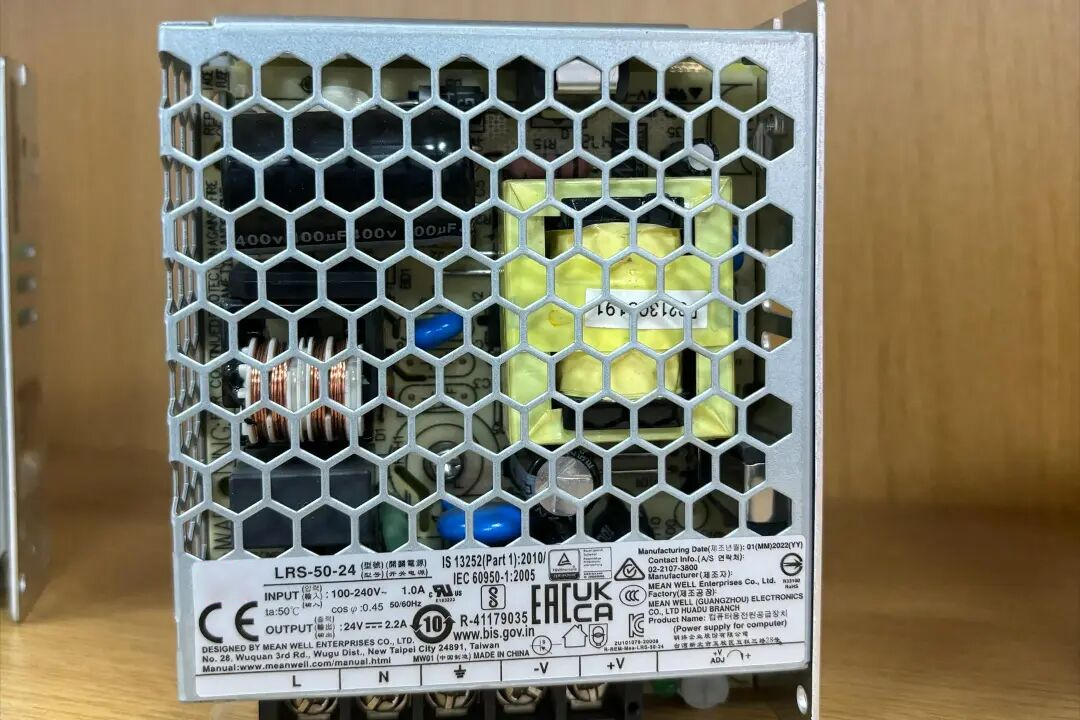
When AC power enters the system, it is first filtered through the EMI circuit and then converted into high-voltage DC through the bridge rectifier and bulk capacitor. The PWM controller then drives the MOSFET at high frequency, transferring energy through the transformer. Finally, the secondary-side rectifier and output filter produce stable DC voltage for the load.
Because this entire process relies on continuous high-frequency switching, even small component degradation can eventually cause instability or complete failure.
Typical Internal Structure of an SMPS
| Functional Section | Main Components | Common Failure Risks |
| AC Input Stage | Fuse, NTC thermistor, EMI filter | Fuse blown, surge damage |
| Rectifier Stage | Bridge rectifier, bulk capacitor | Short circuit, capacitor aging |
| PWM Control Stage | PWM IC, startup resistor | Startup failure |
| Switching Stage | MOSFET | Overheating, breakdown |
| Secondary Output | Rectifier diode, filter capacitor | Low voltage, ripple |
| Feedback Circuit | Optocoupler, TL431 | Overvoltage, instability |

Why Does the Power Supply Have No Output Even Though the Fuse Is Normal?
One of the most frustrating SMPS problems occurs when the power supply appears completely dead, yet the fuse remains intact.
Typically, the technician measures normal AC input voltage, but there is absolutely no DC output. The indicator LED may remain off, and the system shows no signs of startup.
In most cases, this means the power supply has either failed to start or has entered protection mode.
The first step is always checking whether the PWM controller IC is receiving proper startup voltage. Common PWM controllers used in industrial switching power supplies include UC3842, TL494, OB2269, NCP1200, and ICE2QS series chips.
If the startup voltage is missing or too low, the most likely causes include:
- Open startup resistor
- Leakage in the startup capacitor
- Faulty auxiliary power supply winding
- Damaged VCC circuitry
High-value startup resistors are especially prone to aging because they operate continuously under high-voltage stress. Over time, resistance drift or open-circuit failure prevents the PWM controller from reaching its startup threshold.
Once startup voltage is confirmed, the next step is checking whether the PWM controller is generating switching pulses. If no oscillation waveform exists, the PWM IC itself may be damaged, or the protection circuit may be locking the controller.
In many repair shops, experienced technicians replace the PWM controller directly because it is inexpensive and often faster than detailed waveform analysis.
If the PWM controller is operating normally but the power supply still produces no output, attention should shift to the MOSFET switching transistor. A partially damaged MOSFET may still appear normal under static multimeter testing but fail under real switching conditions.
Typical Startup Circuit Failure Components
| Component | Typical Failure | Result |
| Startup resistor | Open circuit | No startup |
| PWM controller IC | No oscillation | No switching |
| MOSFET | Gate leakage or short | No output |
| VCC capacitor | ESR increase | Repeated restart |
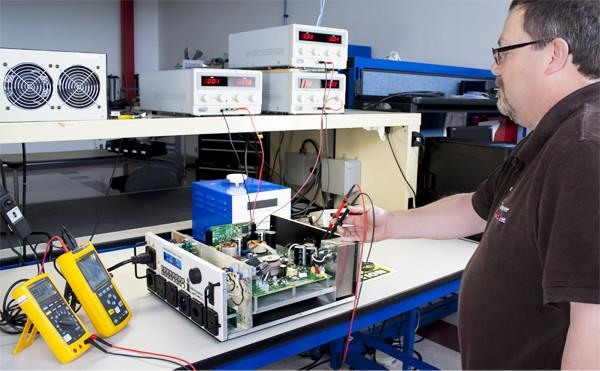
Why Does the Fuse Blow Immediately After Power-On?
A blown fuse almost always indicates a severe short-circuit condition inside the primary side of the switching power supply.
In many cases, the fuse burns instantly when AC power is applied. Sometimes the fuse tube becomes blackened or explodes entirely, often accompanied by visible burn marks or a strong electrical smell.
The first components that should be inspected are the high-voltage bulk capacitor, bridge rectifier, and switching MOSFET.
The bulk capacitor typically operates at around 300V–450V DC and handles significant ripple current. As electrolytic capacitors age, internal pressure rises, ESR increases, and eventually catastrophic failure can occur.
The bridge rectifier should also be checked carefully. If one or more rectifier diodes short internally, AC power effectively becomes a direct short across the input line, immediately destroying the fuse.
However, in modern high-frequency SMPS systems, the switching MOSFET remains the single most common reason for fuse failure.
Power surges, unstable grid voltage, overheating, poor cooling, and lightning spikes can all destroy the MOSFET. Once the MOSFET shorts internally, current rises instantly and the fuse blows for protection.
Unfortunately, MOSFET failure often damages surrounding components simultaneously, including:
- PWM controller IC
- Current sensing resistor
- Gate driver circuitry
- Startup resistors
This is why replacing only the MOSFET frequently results in repeated failure during power-up.
Components Most Commonly Responsible for Fuse Failure
| Failure Source | Failure Probability | Severity |
| MOSFET short circuit | Very High | Critical |
| Bridge rectifier damage | High | Severe |
| Bulk capacitor short | Medium | Severe |
| Lightning surge damage | Medium | Critical |
| NTC thermistor failure | Medium | Moderate |
Why Is the Output Voltage Too High?
Output overvoltage is one of the most dangerous SMPS failures because it can destroy downstream equipment almost instantly.
In industrial automation systems, excessive output voltage may damage PLC controllers, sensors, communication modules, or expensive CNC electronics.
Most switching power supplies regulate output voltage through a closed-loop feedback system. This loop usually contains:
- Sampling resistors
- TL431 precision reference
- Optocoupler isolation feedback
- PWM controller
If any component inside this feedback loop becomes unstable, the PWM controller may incorrectly increase switching duty cycle, causing output voltage to rise uncontrollably.
Optocouplers are particularly vulnerable to aging in long-term industrial applications. Over time, their CTR (current transfer ratio) decreases, causing inaccurate feedback signals.
Similarly, the TL431 precision regulator can drift or fail entirely, resulting in unstable output regulation.
Even a simple resistor value drift in the feedback divider network can significantly alter output voltage.
Because of this, professional technicians usually inspect the entire feedback loop whenever abnormal output voltage appears.
Key Feedback Circuit Components
| Component | Function | Failure Result |
| TL431 | Precision voltage reference | Output drift |
| Optocoupler | Isolated feedback | Overvoltage |
| Sampling resistor | Voltage division | Incorrect regulation |
| PWM controller | Duty cycle control | Unstable output |
Why Is the Output Voltage Too Low?
Low output voltage is one of the most common problems in both industrial and consumer switching power supplies.
In some cases, the power supply starts normally but cannot maintain voltage under load. In other situations, the output repeatedly rises and collapses, causing equipment restart cycles.
One of the first troubleshooting steps is isolating the load from the power supply.
If the voltage returns to normal after disconnecting the load, the problem likely exists in the downstream circuit rather than inside the SMPS itself.
If the voltage remains low even without load, attention should focus on the secondary-side components.
Output rectifier diodes, especially Schottky diodes, are highly stressed components in high-current designs. As these diodes age, their forward voltage increases, efficiency decreases, and excessive heating develops.
Output capacitors are another extremely common failure point. In industrial environments with high ambient temperature, electrolytic capacitors gradually lose capacitance and increase ESR, resulting in excessive ripple voltage and unstable regulation.
Even if the switching MOSFET has not completely failed, increased RDS(on) caused by thermal aging can reduce overall conversion efficiency and output capability.
Typical Capacitor Lifetime at Different Temperatures
| Operating Temperature | Estimated Lifetime |
| 65°C | 60,000+ hours |
| 85°C | 20,000–30,000 hours |
| 105°C | 5,000–10,000 hours |
This is one reason why SIPURUI industrial switching power supplies use long-life low-ESR capacitors designed specifically for continuous industrial operation.
Professional SMPS Repair Tips Used by Experienced Engineers
Experienced repair technicians rarely begin troubleshooting randomly. Instead, they follow a structured diagnostic process.
First, always check for short circuits before applying power. Measuring MOSFETs, rectifiers, and capacitors with a multimeter can prevent catastrophic secondary failures.
Second, many engineers use a 60W–100W incandescent bulb connected in series with the AC input during testing. This acts as a current limiter and protects newly replaced components from exploding if hidden faults remain.
Third, focus on statistically high-failure components first. In real-world repair work, electrolytic capacitors, MOSFETs, optocouplers, and startup resistors account for the majority of switching power supply failures.
Why Are Industrial-Grade SIPURUI Switching Power Supplies More Reliable?
Industrial environments place enormous stress on power conversion systems.
Factors such as:
- High ambient temperature
- Dust contamination
- Continuous operation
- Voltage fluctuations
- Electrical noise
- Mechanical vibration
all increase failure risk.
SIPURUI industrial switching power supplies are designed specifically to address these challenges through:
- High-efficiency topologies
- Optimized heat dissipation
- Industrial-grade MOSFETs
- Long-life capacitors
- Overcurrent protection
- Overvoltage protection
- Short-circuit protection
- Enhanced EMC filtering
These features help improve long-term reliability in demanding industrial applications.

Final Thoughts
Although switching power supplies may initially appear complicated, most failures follow predictable patterns.
By understanding:
- Startup circuits
- PWM switching operation
- Feedback regulation
- Thermal aging behavior
- Protection mechanisms
engineers and technicians can diagnose problems much more efficiently.
In many cases, a small failed capacitor, a degraded optocoupler, or a drifting resistor may be the true reason an entire industrial system shuts down.
For professionals involved in industrial automation, CNC maintenance, LED systems, communication equipment, or embedded electronics, mastering SMPS troubleshooting is an essential technical skill that saves both time and operational cost.