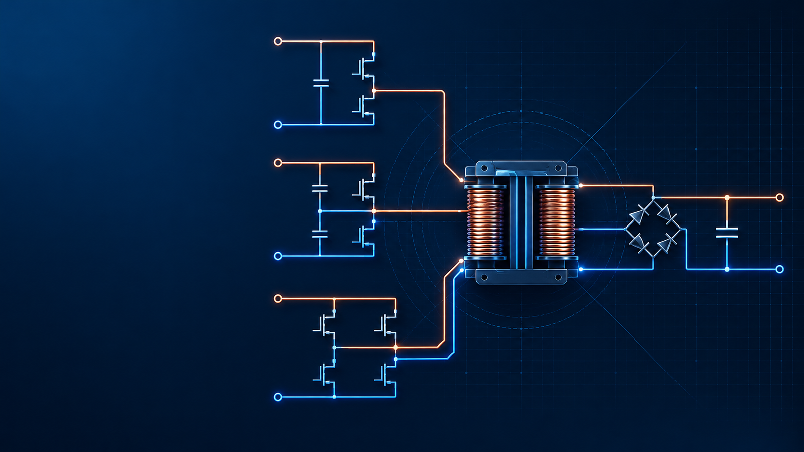
Hard switching is simple and low cost, but MOSFET voltage and current overlap during transitions, creating loss that rises with frequency and bus voltage. Soft switching uses resonance to reduce voltage or current before the switching event, helping high-efficiency supplies reach higher power density with lower thermal stress.
Overview
In a switching power supply, the main MOSFET is often drawn like an ideal switch. In the real circuit, it behaves less politely. It has input and output capacitance, gate charge, body diode behavior, package inductance, PCB parasitics, and a finite transition time. When the device turns on or off, voltage and current can exist at the same time. That overlap becomes heat.
This is the practical starting point for the hard-switching versus soft-switching discussion. Hard switching is simple and cost-effective, which is why it remains common in flyback converters, Buck regulators, Boost stages, and many low-to-medium power supplies. Soft switching adds resonant behavior so the switch changes state under a more favorable condition, usually near zero voltage or zero current. The reward is higher efficiency, lower stress, and a path to higher frequency.
For industrial power supply buyers and design engineers, the choice is not about which technology sounds more advanced. It is about power level, bus voltage, thermal limits, EMI margin, size target, load profile, and cost.
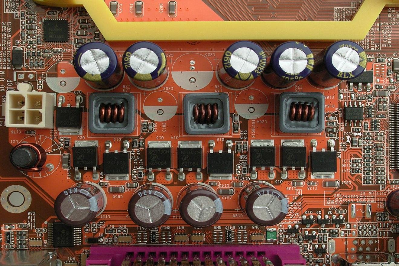
What happens during hard switching?
Hard switching means the controller commands the power switch to turn on or off without first reducing the voltage or current across the device. A PWM controller sends the gate signal according to its timing. The switch has to deal with whatever electrical condition exists at that instant.
During turn-on, the MOSFET gate voltage rises and the channel begins to conduct. At that moment, the drain-source voltage may still be high. Drain current rises while Vds falls. The two curves overlap for a short time, and the instantaneous loss is roughly Vds multiplied by Id during the transition. The same problem appears during turn-off, only in reverse: current is still flowing while Vds rises.
The MOSFET output capacitance, usually discussed as Coss, adds another loss term. When the MOSFET has been off, Coss is charged to a high voltage. In a hard-switched turn-on event, much of that stored energy is dissipated in the MOSFET channel. A simplified estimate is:
`P_Coss = 1/2 x Coss x Vds^2 x fsw`
The exact device behavior is more complex because Coss is voltage-dependent, but the direction is clear. Higher switching frequency increases the number of loss events per second. Higher bus voltage hurts even more, because the stored energy rises with the square of voltage.
Traditional flyback converters are a familiar example. They are inexpensive, compact at modest power, and easy to control. But when the MOSFET turns on with a high drain voltage, Coss energy and leakage-related stress become real thermal problems. Designers often add RCD clamps, RC snubbers, TVS devices, or active clamp circuits to control spikes. Some of that energy is simply burned as heat.
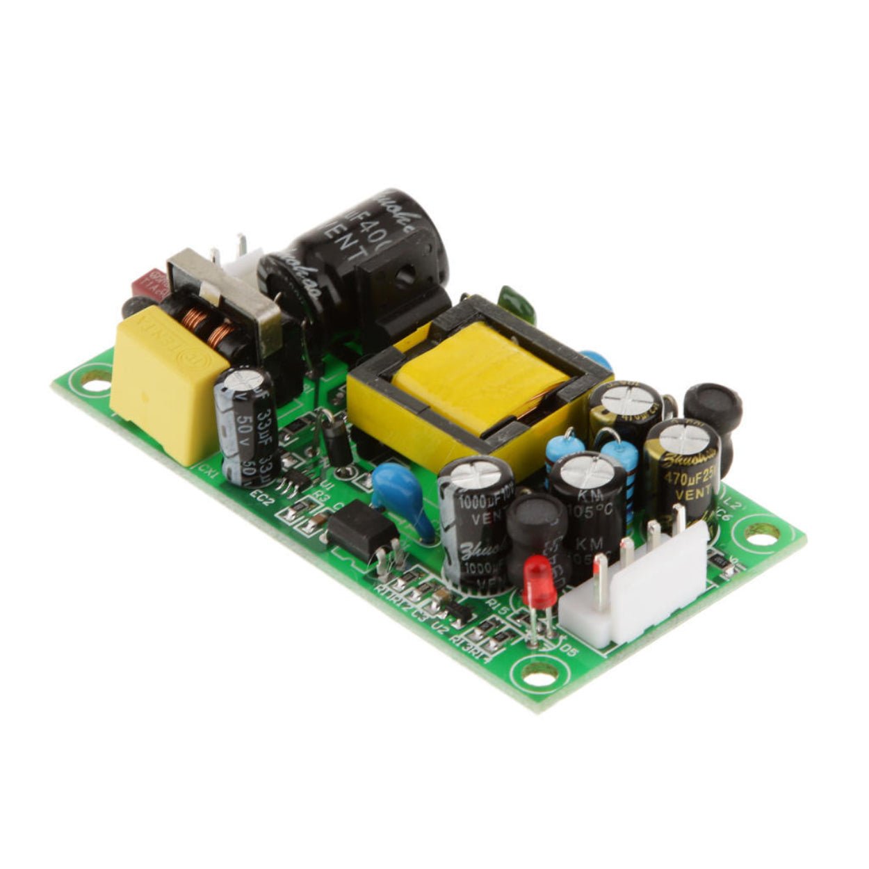
Hard switching still makes sense in many products. A 10 W adapter, a low-cost auxiliary rail, or a board-level Buck converter may not need the extra cost and design effort of soft switching. The issue appears when the design must combine high bus voltage, high current, high frequency, small magnetics, and high efficiency.
The soft-switching idea
Soft switching changes the timing condition around the switch transition. Instead of forcing the device to switch under high voltage and high current, the circuit uses an LC resonance, leakage inductance, magnetizing current, or an added resonant element to move voltage or current close to zero before the switching event.
The two terms engineers meet most often are ZVS and ZCS.
ZVS, or zero-voltage switching, means the MOSFET turns on when the drain-source voltage has already fallen close to zero. This sharply reduces turn-on overlap loss and prevents Coss energy from being dumped directly into the channel. LLC resonant converters and phase-shifted full-bridge converters commonly rely on ZVS for the primary-side switches.
ZCS, or zero-current switching, means the device turns off when current has fallen close to zero. This is especially helpful for devices or operating points where turn-off loss dominates. ZCS is often discussed with resonant converters, diodes, and IGBTs, although MOSFET-based AC-DC power supplies more often focus on ZVS.
Soft switching does not remove all losses. The MOSFET still has Rds(on), gate-drive loss, output capacitance behavior, and body diode considerations. The transformer still has copper loss, core loss, leakage, and insulation constraints. The resonant tank itself carries circulating current. A soft-switched converter can still run hot if the magnetics, layout, device selection, or control range are poorly designed.
The benefit is narrower and more useful: soft switching removes or reduces a large part of the switching-transition loss that blocks high-frequency, high-efficiency designs.

Hard switching vs. soft switching: practical comparison
| Design factor | Hard switching | Soft switching |
|---|---|---|
| Switching condition | Device turns on or off under existing voltage and current | Resonance or stored energy moves voltage or current near zero before switching |
| Main switching loss | Turn-on overlap, turn-off overlap, Coss discharge loss | Much lower turn-on loss with ZVS; lower turn-off loss with ZCS |
| Control style | Usually fixed-frequency PWM with duty-cycle control | Often variable-frequency control, valley switching, or phase-shift control |
| Frequency range | Commonly tens of kHz to around the low hundreds of kHz | Hundreds of kHz and, in some designs, MHz-class operation |
| EMI behavior | Sharp current pulses and voltage edges can increase conducted and radiated noise | Softer transitions can reduce spikes, although layout still matters |
| Magnetics size | Lower frequency usually requires larger transformer and inductors | Higher frequency can reduce magnetic size and improve power density |
| BOM cost | Lower component count and simpler controller | Resonant components, dedicated controllers, and more demanding magnetics |
| Load-range behavior | More predictable across wide load range | ZVS or ZCS may be lost at light load unless the controller manages it |
| Typical topologies | Flyback, Buck, Boost, Forward | LLC, phase-shifted full bridge, quasi-resonant flyback, active-clamp flyback |
This table hides one important detail: soft switching has conditions. It is not a checkbox that guarantees zero loss across every line and load point.
Why high frequency punishes hard switching
Power density improves when switching frequency rises. A higher frequency can reduce transformer size, output inductor size, and sometimes capacitor size. That is attractive for server power supplies, compact industrial supplies, high-power chargers, medical equipment, robotics power modules, and energy storage systems.
Hard switching fights this trend. If a MOSFET has meaningful overlap loss at 65 kHz, increasing the switching frequency to 200 kHz gives the same transition loss event many more chances to occur each second. Coss loss follows the same pattern. At a 400 V DC bus, the voltage-squared term makes the penalty hard to ignore.
This is why a simple hard-switched flyback converter may be fine at low power but struggle as the design pushes into higher power and higher frequency. The MOSFET temperature rises. Snubber losses rise. EMI margin tightens. The transformer may get smaller, but the thermal design gets worse. Eventually the size saved in magnetics comes back as heatsink, spacing, shielding, or derating.
Soft switching gives the designer another route. By moving the switch transition to a low-voltage or low-current point, it becomes possible to raise the operating frequency without paying the full hard-switching penalty.
How LLC converters achieve ZVS
An LLC resonant converter uses a resonant inductor, a resonant capacitor, and the transformer's magnetizing inductance as part of its energy-transfer mechanism. In a half-bridge or full-bridge LLC stage, the primary MOSFETs drive a resonant tank rather than a conventional square-wave transformer input.
When one MOSFET turns off, resonant current continues to flow. That current charges and discharges the output capacitances of the bridge MOSFETs. If enough energy is available, the voltage across the next MOSFET falls to near zero before its gate is driven on. The body diode may conduct briefly and clamp the node. The controller then turns on the MOSFET at a near-zero Vds condition.
This is why LLC converters are widely used in high-efficiency AC-DC supplies. STMicroelectronics describes LLC as a resonant topology where primary switches can achieve ZVS at turn-on, while secondary rectifiers can benefit from ZCS behavior in suitable implementations. In practice, modern high-efficiency designs often combine LLC with synchronous rectification on the secondary side to reduce diode conduction loss.
LLC control is not as straightforward as ordinary PWM flyback control. Output regulation is achieved mainly by changing switching frequency around the resonant tank's gain curve. At light load, the controller may increase frequency, enter burst mode, skip cycles, or use other light-load strategies. If the tank current becomes too small, there may not be enough energy to fully discharge MOSFET capacitance. ZVS can be lost.
That light-load detail matters in real products. A power supply can show excellent efficiency at 50 percent or 100 percent load and still need careful tuning for standby power, no-load input consumption, audible noise, and transient response.
ZVS, ZCS, and quasi-resonant switching are not the same
Engineers sometimes use "soft switching" as if it means only LLC. That causes confusion. LLC is one implementation. The wider category includes several mechanisms.
| Soft-switching method | What it reduces | Common use | Practical limitation |
|---|---|---|---|
| ZVS turn-on | MOSFET turn-on overlap and Coss discharge loss | LLC, phase-shifted full bridge, active-clamp designs | Requires enough circulating or load-related energy to discharge Coss |
| ZCS turn-off | Turn-off overlap loss | Some resonant converters, IGBT applications, rectifier behavior | May increase voltage stress or circulating current depending on topology |
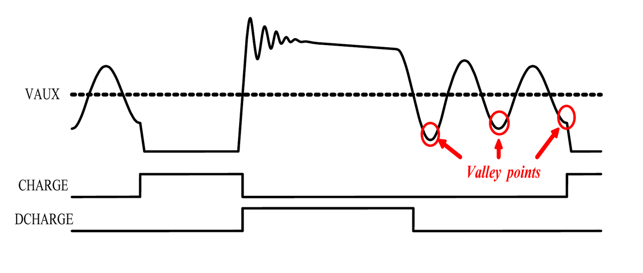
| Quasi-resonant valley switching | Turns on near a drain-voltage valley rather than at peak voltage | QR flyback adapters and chargers | Usually partial soft switching; valley timing changes with line and load |
| Active clamp flyback | Recovers leakage energy and can enable ZVS-like operation | Higher-performance flyback supplies | More components and more demanding control than RCD flyback |
Quasi-resonant flyback deserves special attention. It is common in compact chargers and medium-power adapters because it improves efficiency without the full complexity of an LLC stage. The controller waits for a drain-voltage valley and turns on the MOSFET when Vds is relatively low. This reduces Coss-related turn-on loss. It is not the same as full-range ZVS, and it can lose its advantage as operating conditions change.
Why high-efficiency supplies increasingly use soft switching
The main reason is simple: many modern power supplies are asked to do two hard things at once. They must waste less energy, and they must occupy less space.
Soft switching helps because it lowers the loss that rises directly with switching frequency. Once turn-on loss and Coss discharge loss are reduced, the designer can raise frequency and shrink magnetics without creating an unacceptable MOSFET temperature rise. This is one reason LLC resonant converters appear in server supplies, high-power adapters, communication power systems, industrial AC-DC modules, and energy storage auxiliary supplies.
Soft switching also helps with voltage stress and EMI. Hard switching can produce steep current edges when Coss discharges and when leakage inductance rings with stray capacitance. Snubbers may control the spike, but they often dissipate energy. In a soft-switched converter, part of that energy can be redirected through the resonant process instead of being burned in a clamp resistor.
GaN devices strengthen this trend. GaN transistors can switch very fast and have low charge-related losses compared with many silicon MOSFETs, but fast edges can make layout, EMI, and ringing more difficult. Pairing wide-bandgap devices with soft-switching topologies lets designers use higher frequency more effectively. The device is faster, and the topology prevents the worst switching event from becoming the thermal bottleneck.
The engineering tradeoffs
Soft switching earns its place, but it does not make the design easier.
The first issue is load dependence. ZVS needs energy to charge and discharge MOSFET capacitances. At heavy load, the resonant current is usually sufficient. At very light load, it may not be. The converter can slip back into hard turn-on unless the controller changes operating mode.
The second issue is the control loop. A fixed-frequency PWM converter usually regulates output voltage by changing duty cycle. LLC converters regulate mainly by frequency. The plant gain changes with input voltage, load, and switching frequency. Compensation and transient tuning require more care, especially for wide-input industrial supplies.
The third issue is magnetics. An LLC transformer is not just an isolation transformer. Its magnetizing inductance, leakage or external resonant inductance, winding capacitance, insulation system, and thermal behavior all affect the converter. Manufacturing variation can move the resonant point. A design that looks fine in simulation can become less friendly when transformer tolerances and PCB parasitics arrive.
The fourth issue is cost. A low-cost hard-switched flyback may use a simple controller and a small number of external parts. A soft-switched design may need a resonant controller, tighter magnetics, synchronous rectification, current sensing, protection tuning, and more careful validation. For a 15 W commodity adapter, that cost may not be justified.
When to choose each approach
| Application situation | Better starting point | Reason |
|---|---|---|
| Low-cost auxiliary supply under about 20 W | Hard-switched flyback | Simple, proven, and inexpensive |
| Board-level point-of-load conversion | Hard-switched Buck or synchronous Buck | Compact IC solutions already handle efficiency well |
| 65 W to 120 W adapter with strong cost pressure | QR flyback or active-clamp flyback | Good compromise between efficiency and BOM cost |
| 200 W+ AC-DC supply | LLC resonant converter | Higher efficiency and better power density at higher frequency |
| 500 W to multi-kW industrial or telecom supply | LLC or phase-shifted full bridge | Better suited to high power, high voltage, and thermal limits |
| Wide-load equipment with long standby periods | Case-by-case | Light-load mode and standby requirements may decide the topology |
As a buyer, it is risky to judge a power supply only by topology name. Ask for the efficiency curve across load points, not just the peak number. Check no-load input power, temperature rise at rated load, derating curves, conducted and radiated EMI reports, insulation ratings, and expected lifetime at operating temperature.
As a design engineer, start with the loss budget. If switching loss, snubber loss, or MOSFET temperature dominates the hard-switched design, soft switching is worth serious consideration. If conduction loss, transformer loss, or cost dominates, a soft-switching topology may add complexity without solving the main problem.
Common misunderstandings
Soft switching is not zero loss. It mainly reduces switching-transition loss. Conduction loss, drive loss, transformer loss, rectifier loss, and circulating current remain.
LLC does not guarantee ZVS at every operating point. At light load or during abnormal conditions, there may not be enough resonant current to discharge Coss before turn-on.
Lower EMI is not automatic. Soft transitions help, but poor loop layout, transformer capacitance, diode recovery, bad grounding, and careless heatsink coupling can still fail EMC testing.
Hard switching is not obsolete. It remains the normal choice for many Buck, Boost, flyback, and auxiliary power designs where cost, simplicity, and predictable control matter more than peak efficiency.
ZVS does not remove turn-off loss. It targets turn-on. If turn-off current is high, device selection and gate-drive tuning still matter.
Conclusion
Hard switching forces the power device to turn on and off while voltage and current may overlap. It is simple, economical, and still widely used, but its switching loss rises quickly with frequency and bus voltage. That makes it difficult to build compact, high-power, high-efficiency supplies with a purely hard-switched approach.
Soft switching uses resonance or stored energy to create a better switching condition. ZVS brings MOSFET voltage close to zero before turn-on. ZCS brings current close to zero before turn-off. In LLC resonant converters, phase-shifted full bridges, active-clamp flyback stages, and QR flyback supplies, these methods reduce loss, ease thermal pressure, and support higher power density.
The best choice still depends on the product. For cost-sensitive low-power rails, hard switching may be the right answer. For server, communication, energy storage, high-power charging, and demanding industrial supplies, soft switching is often the practical route to better efficiency and smaller size.
SIPURUI designs and supplies industrial switching power supplies for equipment manufacturers, automation integrators, and B2B power system buyers. If your project needs a compact AC-DC or DC-DC supply with stable performance, thermal margin, and the right topology for the application, topology selection is a good place to start the conversation.
Buyer Checklist
- Compare efficiency across real load points, not only peak efficiency.
- Check MOSFET temperature, snubber loss and thermal derating before choosing a hard-switched design.
- Confirm whether ZVS or ZCS is maintained at light load, low line, high line and abnormal conditions.
- Review EMI reports, layout quality, magnetics tolerance and lifetime data before procurement.