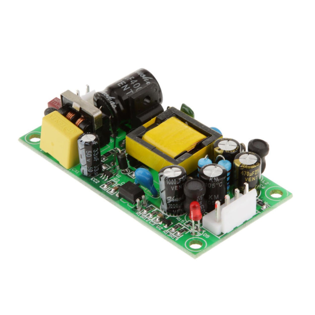
Slow voltage drift in a switching power supply usually points to aging capacitors or a feedback-loop problem, not an immediate PWM controller failure. This guide explains how to diagnose the fault safely and verify the repair under load.
Overview
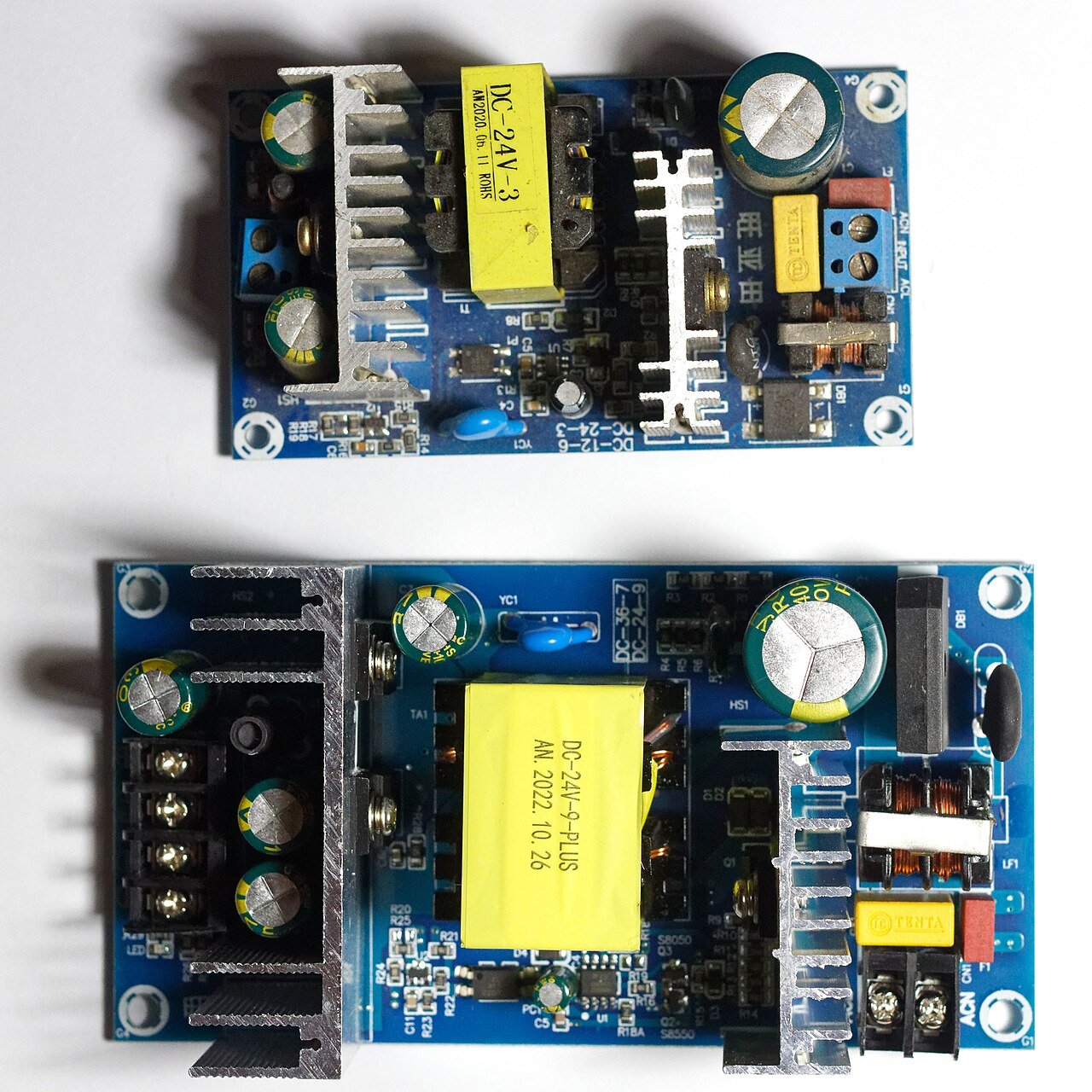
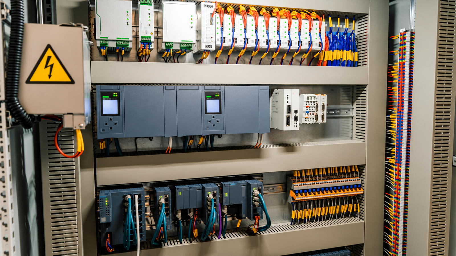
Slow output voltage drift is one of the more awkward switching power supply faults to diagnose. The unit may start at the correct voltage, pass a quick no-load check, and then move out of tolerance after several minutes under load. In automation panels, LED equipment, communications devices, and small industrial machines, that kind of drift can look like a control problem long before anyone suspects the power supply.
This guide turns the repair process into a practical sequence: make the board safe, understand what the feedback loop is trying to do, check the secondary side first, and use dynamic measurements to catch parts that only misbehave after they warm up.
Start with safety, not the meter
An offline switching power supply can carry about 300 VDC on the primary bulk capacitor after rectifying 220 VAC mains. That charge can remain after the plug is removed. Treat the primary side as hazardous until you have verified otherwise.
Before inspection, unplug the supply and discharge the primary high-voltage electrolytic capacitor through a resistor. A 100 kOhm, 2 W or higher resistor held with insulated clips is a common shop method. Hold it across the capacitor terminals for several seconds, then confirm with a meter. Do not short the capacitor with a wire or screwdriver. The spark can damage the board and injure the technician.
During powered tests, keep one hand away from the circuit, use an insulated bench surface, and avoid touching any metal on the board. When possible, connect the meter leads while the unit is off, secure them with clips or tape, and only then power the supply. For first power-up after repair, a current limiter such as an incandescent lamp in series with the AC line can reduce damage if a short remains.
Most slow-drift problems are found on the secondary low-voltage side: output capacitors, the sampling divider, TL431 reference circuit, optocoupler, and compensation parts. Starting there reduces exposure to the high-voltage primary side and usually gets you to the fault faster.
Why an SMPS output drifts slowly
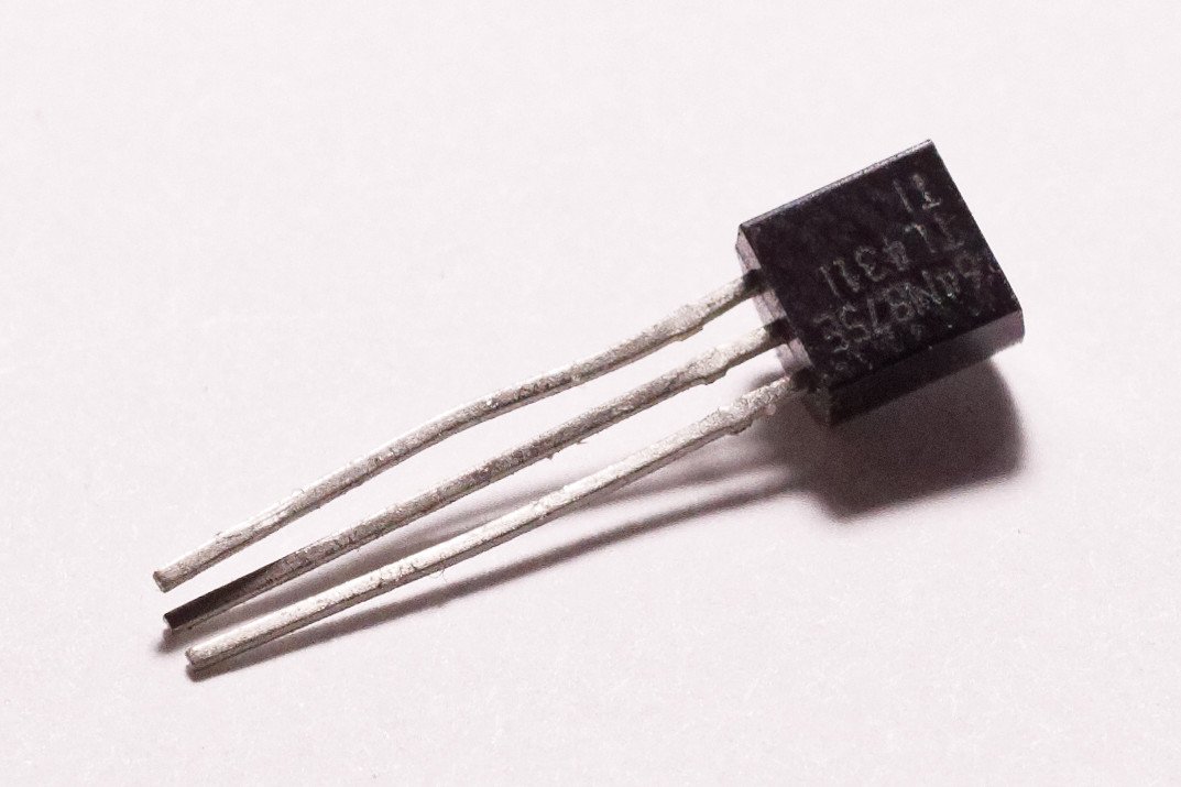
In many isolated AC-DC supplies, the output voltage is regulated by a feedback loop. The secondary output is sampled by a resistor divider. That sampled voltage is compared with the TL431 reference, typically 2.5 V. The TL431 then drives the LED side of an optocoupler, and the optocoupler transfers the error signal back to the PWM controller on the primary side. The controller changes duty cycle to pull the output back toward its nominal value.
If the output drifts slowly rather than failing suddenly, the loop has not disappeared. A part inside the loop is changing value with temperature, time, leakage, or load. The usual suspects are electrolytic capacitors, divider resistors, the TL431, the optocoupler, and small compensation capacitors around the feedback path.
| Symptom pattern | Likely area | What usually changes |
|---|---|---|
| Voltage starts normal, then rises | Sampling divider, TL431, optocoupler transfer ratio | Reference current or feedback strength becomes too weak |
| Voltage starts normal, then falls under load | Output capacitor, primary bulk capacitor, optocoupler leakage | Filtering or energy storage weakens as temperature rises |
| Ripple increases with time | Output electrolytic capacitor | ESR rises or capacitance falls |
| Voltage jumps when a part is heated or cooled | Temperature-sensitive feedback part | Resistor drift, TL431 shift, optocoupler aging, capacitor leakage |

First inspection with power removed
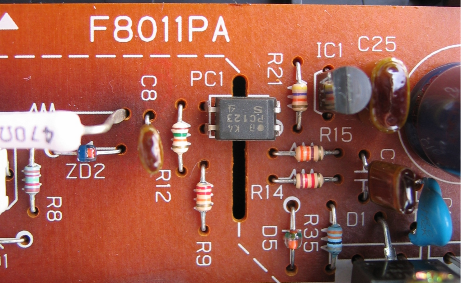
After discharging the bulk capacitor, inspect the board under good light. Many drift faults leave visible clues.
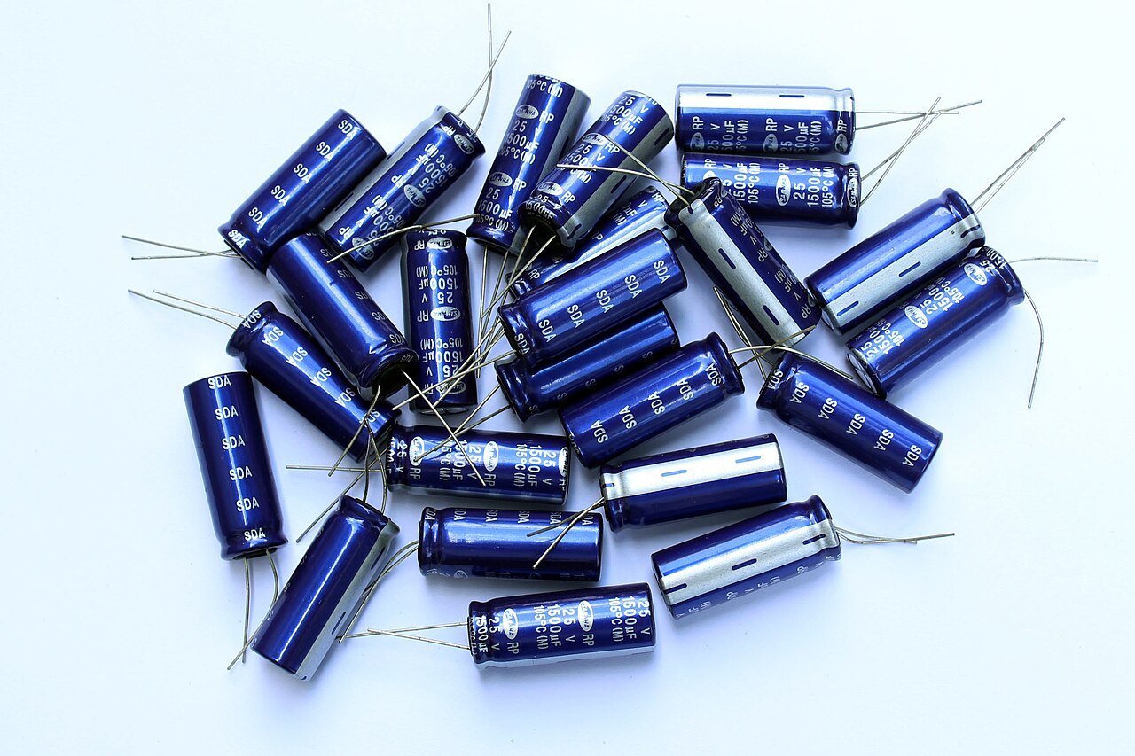
Start at the output electrolytic capacitors. Look for bulged tops, leakage, shrunken sleeves, corroded leads, or discoloration on the PCB. In compact power supplies, the output capacitors often sit near rectifiers, heatsinks, or transformers. Heat dries them out. As capacitance falls and ESR rises, the supply may still start, but the output becomes unstable under load.
Check the feedback loop next. Look closely at the TL431, the optocoupler, the output-voltage divider resistors, and the small capacitors connected around the TL431 cathode and reference pin. Cracked solder joints can add resistance as the board warms, and that changing contact resistance is enough to move the output voltage. Gently press suspect parts with an insulated tool while watching the solder joints.
Offline measurements that are worth doing
Offline checks will not catch every thermal fault, but they can remove the obvious problems before live testing.
For the output-voltage sampling divider, lift one end of each resistor when accuracy matters. The divider normally runs from output positive to the TL431 reference pin and then to output ground. The basic relationship is:
`Vout = 2.5 V x (1 + upper resistor / lower resistor)`
If the lower resistor increases in value, the sampled voltage falls and the supply may drive the output higher. If the upper resistor increases, the sampled voltage rises and the output may fall. Replace drifted parts with 1% metal film resistors. Carbon film parts are a poor choice in a feedback divider because their temperature behavior is less predictable.
For the TL431, use the diode range as a rough screen. A healthy device often shows diode-like conduction from anode to cathode and from anode to reference, with no reverse leakage in a simple meter test. This only finds gross damage. A TL431 that shifts its reference voltage when warm may test normally at room temperature.
For a common PC817-type optocoupler, the input LED should show roughly 1.1 to 1.3 V forward drop and block in reverse. The transistor side should not show leakage in either direction during a simple diode check. Again, this does not prove current transfer ratio. An aged optocoupler can lose transfer gain and still look fine on a basic meter.
Electrolytic capacitors can be checked for severe leakage with a high-resistance range, but this is only a coarse test. If the supply has slow drift plus rising ripple, replacement with a high-frequency, low-ESR capacitor of proper temperature rating is often more reliable than arguing with a meter reading.
Dynamic testing under load
Slow drift is a powered, warm-board fault. Test it under a load that resembles real service. A 12 V output can be checked with a suitable lamp or power resistor. A 5 V output needs a resistor or electronic load rated for the current and heat involved. No-load readings can be misleading because some supplies regulate poorly without minimum load.
Connect the voltmeter to the output before power-up and record the voltage for 5 to 10 minutes. Note whether it climbs or falls, how many millivolts per minute it moves, and whether the rate changes as the board warms. This simple log gives the repair a direction instead of turning the bench into a guessing game.
Temperature disturbance is especially useful. Warm one suspect part at a time with low heat and distance. Do not overheat plastic packages or electrolytic capacitors. If the output voltage jumps when the TL431, divider resistor, optocoupler, or output capacitor is warmed, you have probably found the neighborhood. Cooling a part with a small amount of isopropyl alcohol on a swab can confirm the direction by making the voltage move back.
| Measurement point | Normal behavior | What a drifting reading suggests |
|---|---|---|
| Output voltage | Stable after start-up, within specification under load | Direction and rate point to feedback or storage problems |
| TL431 reference pin | About 2.50 V and steady | Moving reference voltage suggests TL431, divider, or leakage near the reference pin |
| Optocoupler LED side | Often around 1.1 to 1.3 V while regulating | Movement inconsistent with output correction suggests secondary feedback trouble |
| Output ripple | Typically low and stable for a healthy unit | Ripple over 100 mV or rising ripple strongly suggests output capacitor aging |
Use the TL431 reference pin to split the fault
The TL431 reference pin is one of the best checkpoints because it separates the sampling side from the rest of the feedback path. Measure it from secondary ground to the TL431 reference pin while the supply is operating under load.
If the reference pin itself slowly rises or falls away from about 2.50 V, focus on the TL431, the divider network, and any capacitor tied to the reference node. Leakage around this node can be small and still matter.
If the TL431 reference stays steady while the output voltage drifts, the problem may be after the reference comparison: optocoupler current transfer, pull-up resistance, compensation, PWM feedback behavior, or primary-side energy storage. At that point, replacing the optocoupler is often a reasonable test because aging transfer ratio can be difficult to prove with simple bench tools.
If the voltage slowly rises
A rising output normally means the control system is allowing too much duty cycle or too little corrective feedback. Check the lower resistor of the sampling divider first. If it has drifted high, the TL431 reference pin sees less voltage than it should and the supply behaves as if the output is too low.
Next, replace suspect output capacitors. Leakage that increases with temperature can pull the feedback node in the wrong direction, and poor filtering can confuse regulation under load. Use the same capacitance or a close value, equal or higher voltage rating, low ESR type, and a temperature rating suitable for the enclosure. Do not reduce voltage rating.
If the TL431 reference voltage rises above the expected window and continues moving, replace the TL431 with a known-good part from a reputable source. Low-grade references and counterfeit optocouplers can create the same problem again.
Finally, consider the optocoupler. When its transfer ratio falls with age, the primary controller receives a weaker correction signal for the same LED current. The controller then keeps driving harder, and the output rises.
If the voltage slowly falls
A falling output under load often starts with the output capacitors. When capacitance is low or ESR is high, the supply may hold voltage briefly and then sag as heat builds. Replace output electrolytics before chasing rare controller faults.
Check the upper divider resistor. If it has drifted high, the TL431 reference pin is driven higher for a given output voltage, so the loop may reduce duty cycle too much. A TL431 with leakage or a reference that falls when hot can create a similar symptom.
Optocoupler output-side leakage can also make the primary controller think the output is too high, causing it to pull drive back. If the basic diode test shows leakage between the transistor pins, replace it. If the meter test is clean but the symptom still points there, substitution is faster than trying to characterize the part on the board.
Do not ignore the primary bulk capacitor if the output falls mainly under load. A tired high-voltage electrolytic can reduce available bus energy and make the supply look weak after warm-up. This check belongs later in the sequence because it involves the hazardous primary side.
Repair order that saves time
For a slow-drift fault with no obvious burn damage, a practical replacement order is:
| Repair action | Why it comes early | Notes |
|---|---|---|
| Replace output electrolytic capacitors | High failure rate, strong effect on ripple and load stability | Use low-ESR, correct temperature rating, equal or higher voltage rating |
| Recheck and resolder feedback joints | Heat-sensitive cracks can imitate component drift | Focus on TL431, optocoupler, divider, and output connector |
| Measure or replace divider resistors | Small resistance changes directly alter output setpoint | Prefer 1% metal film parts |
| Replace optocoupler | Aging transfer ratio is hard to measure in circuit | Use reputable PC817-equivalent or specified original part |
| Replace TL431 and compensation capacitor | Reference or leakage faults can be temperature dependent | Watch pinout; TL431 variants are not always laid out the same |
| Check primary bulk capacitor | Relevant when voltage sags under load | Discharge and verify before handling |
After replacing parts, inspect polarity and orientation before applying power. Electrolytic capacitors, TL431 packages, and optocouplers are easy to install incorrectly when working from memory. Use the board markings and the datasheet, not only the shape of the old component.
Verification before the unit goes back into service
First power the unit through a current limiter and check the output without load. If the voltage behaves normally, run it for about 15 minutes and confirm that it stays within the expected tolerance. Then repeat the test with a rated dummy load or an application-like load for at least 10 minutes. A supply that is stable only at no load is not repaired.
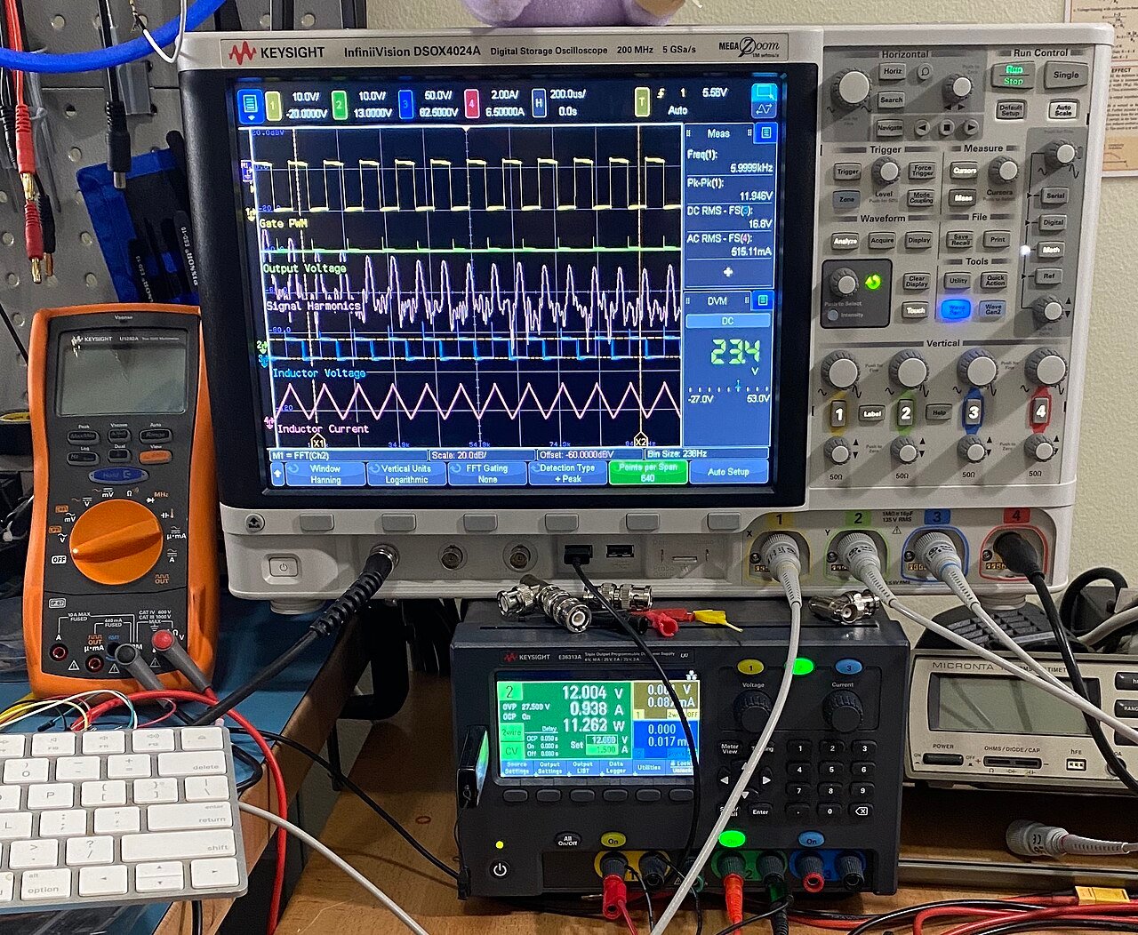
Measure ripple if you have a scope. If you only have a multimeter, the AC millivolt range across the output capacitor can still give a rough warning, but it will not show switching spikes accurately. Rising ripple during the warm-up period is a strong reason to revisit the output capacitors and solder joints.
Clean flux residue and any alcohol left from cooling tests before reassembly. Flux around high-impedance feedback nodes can become a leakage path in humid environments.
Common mistakes to avoid
Do not replace the PWM controller first. Controllers such as UC3842-style parts can fail, but they are rarely the first cause of slow output drift. The secondary feedback loop and electrolytic capacitors deserve attention first.
Do not mix primary ground and secondary ground during measurement. In an isolated supply, those grounds are not the same node. A careless meter connection can damage the instrument or expose the technician to shock.
Do not install general-purpose electrolytics where the original design used low-ESR output capacitors. They may work for a few minutes and fail early from heat and ripple current. In industrial equipment, that kind of shortcut often returns as a field failure.
For OEMs and maintenance teams, the larger lesson is simple: output-voltage drift is often a component aging and feedback-loop stability issue, not a mysterious control-board fault. When selecting replacement power supplies for automation cabinets, LED systems, and equipment builds, check output tolerance, ripple specification, capacitor temperature rating, and supplier consistency. SIPURUI can help match standard AC-DC and DC-DC switching power supplies to real installation conditions, especially where long service life matters more than the lowest unit price.
Buyer Checklist
- Discharge and verify the primary bulk capacitor before handling the board.
- Inspect output electrolytics, feedback solder joints, TL431, optocoupler and divider resistors first.
- Log output voltage drift under realistic load for 5 to 10 minutes.
- Check TL431 reference voltage and output ripple while the board warms up.
- Use low-ESR capacitors with correct voltage and temperature ratings when replacing output parts.