A practical guide to non-magnetic causes of SMPS output noise, including MLCC vibration, PCB resonance, poor contacts, loop instability, rectifier ringing, safety capacitors, and load interaction.
Overview
A whining, buzzing, hissing, or intermittent clicking sound from a switching power supply is often blamed on the transformer core. That first suspicion is understandable. Magnetostriction in transformers and power inductors can create audible vibration, and the transformer is usually the part people hear most clearly.
In real troubleshooting, however, the transformer is sometimes only the loudspeaker. The original vibration may start in a ceramic output capacitor, a loose output terminal, a copper trace, a feedback loop problem, a rectifier switching spike, or even the equipment connected to the power supply. The vibration travels through copper, solder, the PCB, the enclosure, and the magnetic components. By the time it reaches a technician's ear, the sound may appear to come from the transformer even when the magnetic core is not the root cause.
This article looks at audible noise from the output side of an SMPS. It is written for engineers, automation integrators, equipment builders, and buyers who need to decide whether the noise is only an acoustic nuisance or a sign of electrical stress that can shorten service life.
Audible noise is often a symptom, not the failure itself
Most switching supplies operate above the normal human hearing range. When a unit becomes audible, something has usually moved energy into the 20 Hz to 20 kHz band, modulated a high-frequency waveform at an audio-rate envelope, or excited a mechanical resonance in a component or structure.
That is why sound location can mislead the investigation. A ceramic capacitor can vibrate the board. The board can excite the transformer pins. The metal case can amplify the result. A technician hears the transformer area and reaches for glue, but the circuit condition that created the noise remains unchanged.
A true magnetic-core noise usually changes when the core temperature, air gap pressure, DC bias, or winding load changes. If gently pressing the transformer core with an insulated plastic tool alters the sound, the magnetic part deserves attention. If pressing the core does almost nothing, while pressing the output capacitors, terminal block, or PCB changes the noise, the fault path is probably elsewhere.
Common non-magnetic causes at a glance
| Audible behavior | Likely non-magnetic source | Typical clue | Main risk |
|---|---|---|---|
| Low buzz that grows with load | MLCC output capacitor vibration | Quiet at no load, louder as ripple current rises | Higher output ripple, capacitor heating, accelerated aging |
| Sharp light-load squeal | Burst mode, loop behavior, or ceramic capacitor strain | Noise fades at medium or full load | Poor transient response, audio-band modulation, stress during load steps |
| Intermittent sizzling or crackling | Cold solder joint, loose connector, micro-arcing | Changes with tapping, bending, or temperature | Very high risk of heating, carbonization, board damage, load dropout |
| Fine high-frequency whine through output leads | Cable or PCB parasitic LC resonance | Sound changes when cables are moved or touched | Radiated/conducted EMI, output spikes, sensitive-load errors |
| Click or buzz at start-up or load step | Rectifier recovery, synchronous MOSFET ringing, inrush excitation | Appears only during dynamic transitions | Extra switching loss and voltage overshoot |
| Rhythmic buzz with output voltage movement | Feedback-loop oscillation | Scope shows low-frequency envelope on DC output | Very high risk of overvoltage, instability, load resets |
| Thin hiss in standby | X/Y safety capacitor vibration or common-mode noise | Weak relationship with output load | Common-mode noise concern, usually not immediate destructive failure |
| Noise only with the real load attached | Power supply and load impedance interaction | Resistive dummy load is quiet | System oscillation, output stress, nuisance resets |

1. MLCC piezoelectric vibration
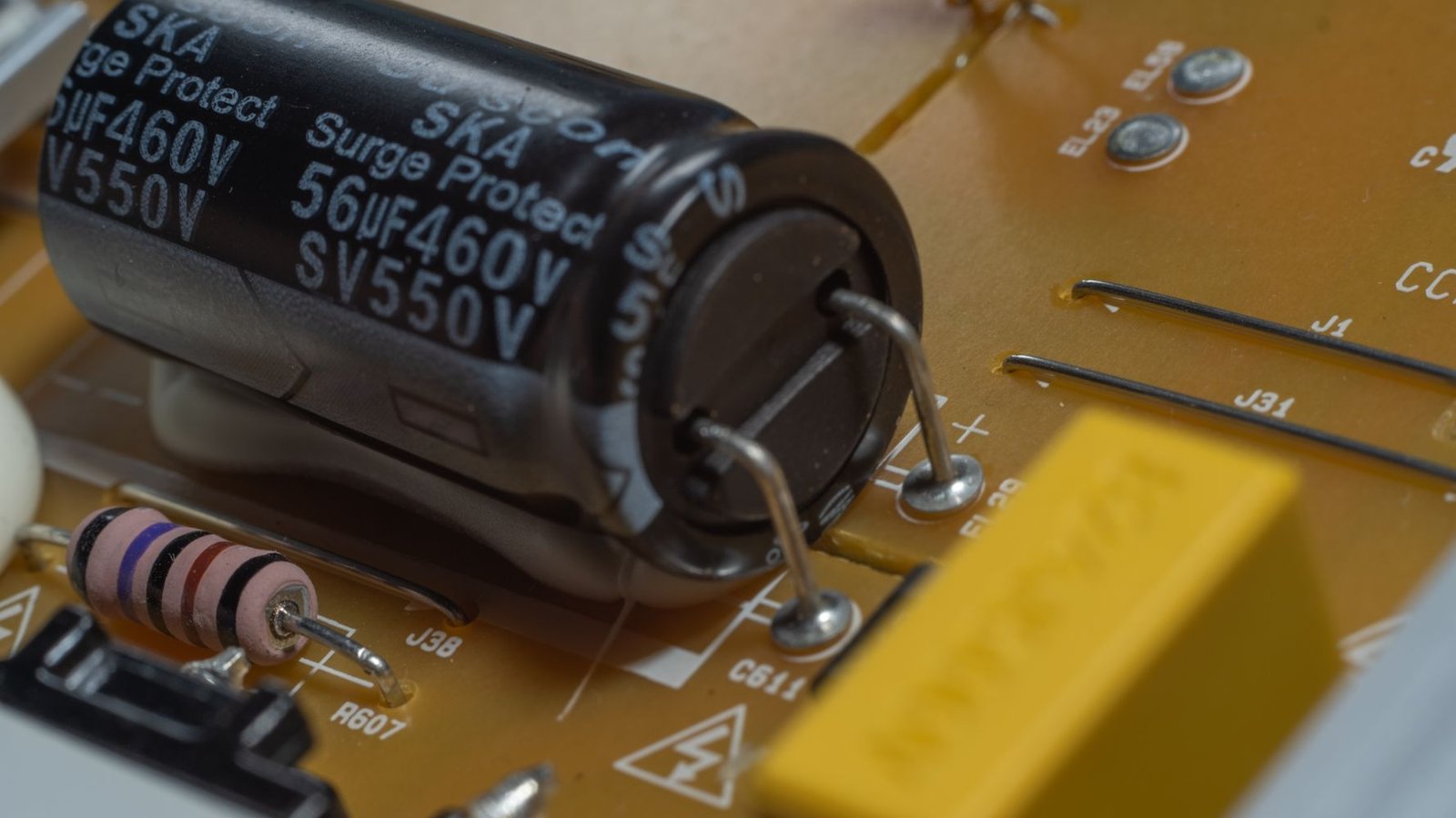
Multilayer ceramic capacitors are one of the most common non-magnetic acoustic sources in output circuits. The ceramic dielectric can behave piezoelectrically: changing voltage causes tiny mechanical deformation. The deformation is small, but the capacitor is soldered to a PCB, and the PCB can radiate sound like a thin panel.
The clue is load dependency. At no load, output ripple current may be low and the unit may stay quiet. Add load current, and the ripple current through the capacitor bank increases. A buzzing or frying sound appears, sometimes strongest near the transformer because the board carries the vibration there.
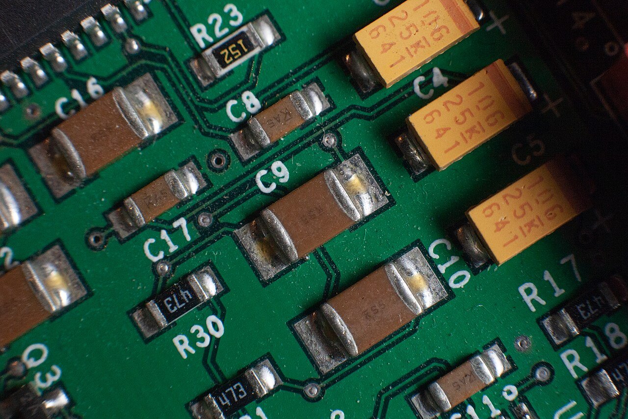
Large high-capacitance MLCCs, especially in high-ripple positions, are more likely to create audible vibration. Replacing every output capacitor with more ceramic capacitance can backfire. It may move the resonance rather than remove the excitation. A better fix usually combines ripple-current review, capacitor mix, layout changes, and damping.
| Check | What to look for | Practical response |
|---|---|---|
| Press test with insulated tool | Noise drops when an MLCC body or nearby PCB area is held | Confirm with a temporary capacitor substitution |
| Output ripple measurement | High ripple or audio-frequency envelope under load | Review capacitance, ESR, ESL, and loop compensation |
| Capacitor substitution | Noise falls when ceramic capacitors are replaced or paralleled with electrolytic/polymer parts | Use a mixed output capacitor network, not only larger MLCCs |
| Thermal scan | Capacitor bank runs warmer than expected | Increase ripple-current margin and check load transients |
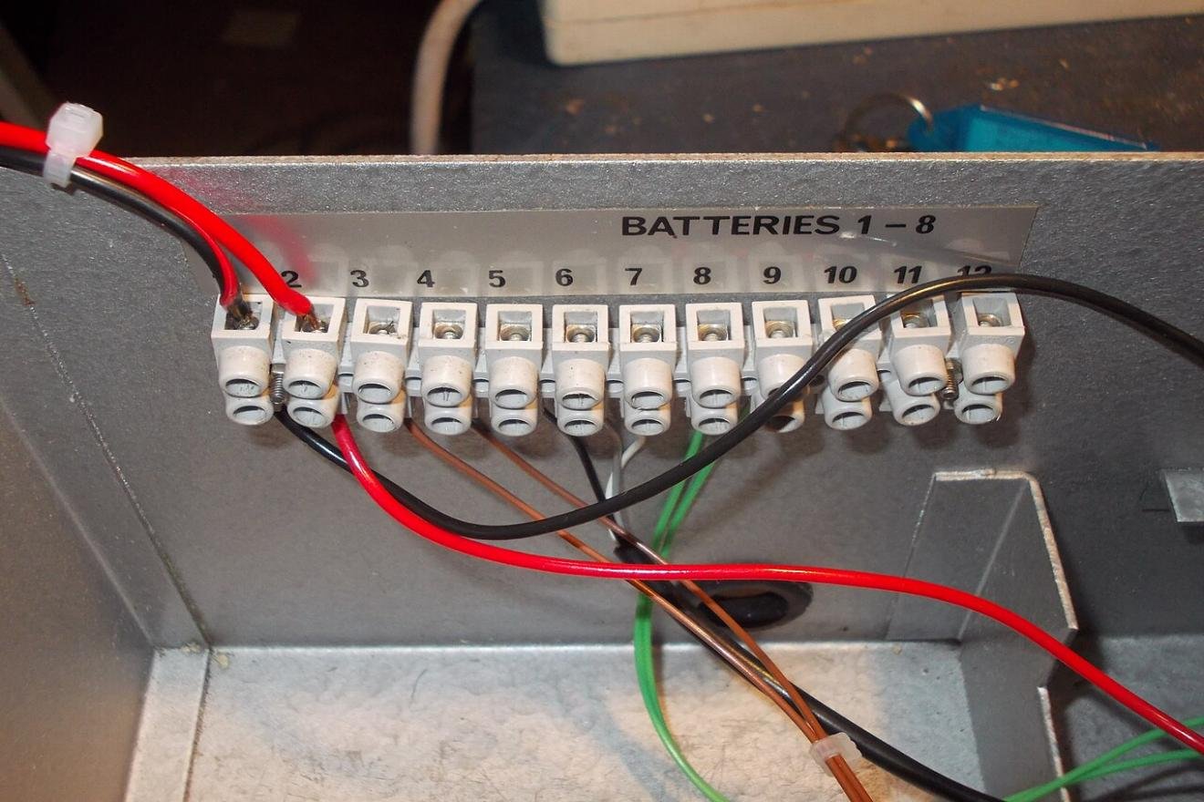
2. PCB copper and output cable resonance
Output traces and wires are not ideal conductors. They add parasitic inductance. Output capacitors add capacitance, ESR, and ESL. Together, the power loop can form an LC network that rings when switching noise, diode recovery, or load current pulses excite it.
This type of noise can be surprisingly directional. Touching the output cable may change the sound. Shortening the cable, twisting the output pair, adding a small damping network, or moving the load connection point may reduce it. The schematic may look correct while the physical power loop is too large.
The electrical risk is not just sound. Resonance can raise output ripple and high-frequency spikes. In a control cabinet, that noise may couple into sensors, analog input modules, communication lines, or a PLC power rail. For OEM equipment, this is where a small acoustic complaint becomes a system reliability problem.
3. Poor output solder joints and loose terminals
Intermittent sizzling or crackling deserves immediate attention. Output terminals, connector pins, and high-current solder joints can develop contact resistance from cold solder, insufficient wetting, oxidation, mechanical stress, or repeated thermal cycling.
A static meter test may show nothing unusual. Under load, the bad contact heats and moves slightly. In severe cases, micro-arcing creates a fine crackle. The fault may disappear after warm-up because metal expansion temporarily improves pressure, then return after cooling or vibration.
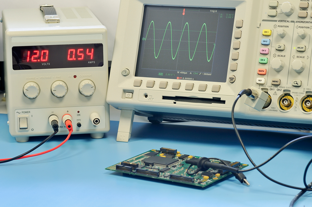
This is a high-risk condition. It can char the board, burn a connector, cause random output drops, and damage the downstream load. Treat it as an electrical fault, not a cosmetic noise issue. Inspect under magnification, reflow suspect joints, check terminal torque, measure temperature rise, and load-test the output path.
4. Feedback-loop oscillation
A power supply can show the correct average voltage on a multimeter while its output is oscillating. The meter hides the problem by averaging. On an oscilloscope, the DC output may carry a low-frequency envelope, often in the hundreds of hertz to several kilohertz range. That envelope can drive capacitors, copper, rectifiers, and magnetic parts into audible vibration.
Loop-related noise often changes with load steps, input voltage, temperature, and output capacitor type. Check the TL431 or error amplifier network, optocoupler behavior, compensation RC parts, output capacitor ESR, and any remote-sense wiring. A load-step test tells more than a steady full-load measurement.
If the loop is unstable, glue is the wrong repair. It may lower the sound level while leaving output ripple, overshoot, and repeated current stress in place. For safety-critical or high-value loads, keep the unit out of service until the loop response is understood.
5. Rectifier recovery and synchronous MOSFET ringing
Output rectifiers and synchronous MOSFETs can create sharp current and voltage transitions. A diode with poor recovery behavior, an overly fast MOSFET edge, or an unsuitable gate resistor can excite ringing through package inductance, transformer leakage inductance, PCB parasitics, and output capacitance.
The sound may appear during start-up, plug-in, load removal, or fast load steps, while steady operation seems quiet. A standard DMM will miss it. Probe the rectifier or MOSFET switching node with proper high-voltage practice, short ground connections, and a bandwidth setting suitable for ringing. If the waveform shows severe overshoot, evaluate snubbers, clamp networks, diode selection, gate resistance, and layout.
6. X/Y safety capacitor acoustic noise and common-mode stress
Safety capacitors can also vibrate, particularly when common-mode noise is high. The audible result is often a thin hiss or faint squeal that exists even in standby. Load changes may affect it only slightly.
This symptom is usually less destructive than arcing or loop oscillation, but it still points to common-mode energy that may travel along output cables. For sensitive instrumentation, medical-adjacent equipment, or long cable runs, review the common-mode choke, Y-capacitor value and placement, shield termination, and conducted EMI performance.
7. Load and power supply impedance interaction
Some noise problems are not inside the supply alone. A unit may run quietly with no load and with a resistive dummy load, then squeal as soon as it powers the real machine. Loads with large input capacitors, downstream DC-DC converters, motor drives, or pulsed current profiles can interact with the supply output impedance.
The result is a system-level resonance. The load injects current pulses or negative-impedance behavior back into the supply output network. The supply responds, the load reacts, and the two excite each other. In the field, this often looks like a bad power supply even when the power supply passes bench tests.
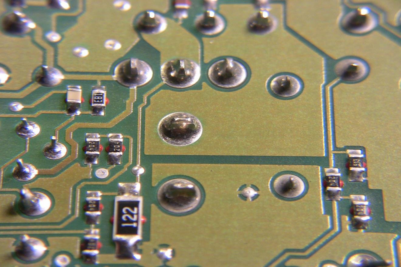
Test with the real load, a resistive dummy load, and an electronic load if available. If only the real load creates noise, try adding damping, a small series resistor, an output ferrite bead rated for DC current, or an intermediate filter designed with stability in mind. Do not add large capacitance at the load input without checking the control-loop effect.
A practical troubleshooting sequence
| Step | Action | Why it matters |
|---|---|---|
| 1 | Inspect output terminals, solder joints, connector fit, and board discoloration | Crackling or intermittent noise can signal heat and arcing |
| 2 | Use an insulated plastic tool to press the transformer, output inductors, MLCCs, terminal blocks, and PCB areas | Separates the loudest acoustic point from the real vibration source |
| 3 | Compare no load, light load, half load, full load, and the real end load | Noise that tracks load condition narrows the suspect list |
| 4 | Measure output ripple with an oscilloscope, not only a multimeter | Average DC voltage can look normal while ripple or oscillation is severe |
| 5 | Check start-up, shutdown, and load-step waveforms | Rectifier recovery and MOSFET ringing often appear only during transitions |
| 6 | Substitute output capacitor types temporarily | A change in sound points toward MLCC acoustic behavior or capacitor-network stability |
| 7 | Repair the electrical cause before adding adhesive or potting | Mechanical damping can hide a fault that still stresses components |
Design choices that reduce non-magnetic noise
Start with the output capacitor network. Use MLCCs where their low ESR and ESL help, but avoid making the entire output bank from large ceramic capacitors in noise-sensitive designs. Add electrolytic or polymer capacitance where damping and ripple-current capacity are useful. Check the ripple-current rating, DC bias derating, temperature rise, and the control-loop assumptions tied to ESR.
Keep the high-current output loop compact. The rectifier or synchronous MOSFET, transformer secondary, and first output capacitor should sit close together with a short return path. Wide copper is good, but loop area and current path geometry matter just as much. Keep noisy power copper away from feedback-sense traces.
Validate the loop across input voltage, load range, temperature, and production capacitor tolerance. Light-load burst mode should also be reviewed for audio-band behavior. In many supplies, the customer hears the unit at night, in standby, or inside a quiet control panel, not during full-load lab testing.
For rectifiers and synchronous MOSFETs, choose parts and gate networks that control ringing instead of only chasing efficiency. A slightly slower edge or a well-placed RC snubber can be cheaper than field returns caused by acoustic complaints and EMI failures.
For OEM projects, test with the real load early. A power supply that looks perfect on a bench resistor can behave differently when connected to a motor controller, LED driver, communication module, or pulsed actuator bank.
Common repair mistakes
The first mistake is treating every noise as transformer-core noise. Adhesive can reduce vibration, but it cannot fix ripple current, poor soldering, loop instability, or a bad load interaction.
The second mistake is trusting a normal DMM reading. Audible noise is often tied to ripple, burst packets, ringing, or low-frequency oscillation. A scope is the right tool.
The third mistake is assuming MLCC noise is harmless. Mild acoustic noise may be acceptable in some applications, but loud MLCC vibration under load can point to high ripple current or a capacitor network that is working harder than expected.
Conclusion
Switching power supply noise should not be reduced to one explanation. Transformers and inductors can make sound, but output capacitors, PCB structures, connectors, control-loop behavior, rectifiers, safety capacitors, and the end load can all create audible symptoms.
The better workflow is simple: find the vibrating part, reproduce the noise under controlled load conditions, observe the waveform, then fix the electrical cause. Physical damping has a place, but only after the circuit stress is understood.
For industrial equipment builders and power supply buyers, this matters because audible noise can indicate reliability risk before a failure appears. SIPURUI supports switching power supply selection for control cabinets, automation equipment, and OEM systems where stable output behavior, practical derating, and consistent production quality matter as much as nameplate voltage and current.
Buyer Checklist
- Check whether the noise changes with real load, dummy load, cable movement, tapping, temperature, or start-up.
- Inspect output MLCCs, PCB copper, solder joints, terminal torque, rectifier behavior, and feedback-loop stability.
- Use an oscilloscope to look for ripple, ringing, burst packets, and low-frequency envelopes that a DMM will hide.
- Treat sizzling, crackling, output drops, overheating, or visible discoloration as electrical fault signs.
- For OEM projects, test the power supply with the real equipment load before final model approval.